
|
1.Use the following special tools to hold the camshaft sprocket.
- Front hub and flange yoke holder (MB990767)
- Pin (MD998719)
2.Loosen the camshaft sprocket mounting bolt and remove the camshaft sprocket.
|
|
|
1.With the hose installed, remove the power steering oil pump assembly from the engine assembly.
|
|
|
2.After removing the power steering oil pump assembly, secure it with a cord in the location where the removal and installation of the cylinder head assembly cannot be hindered.
|
|
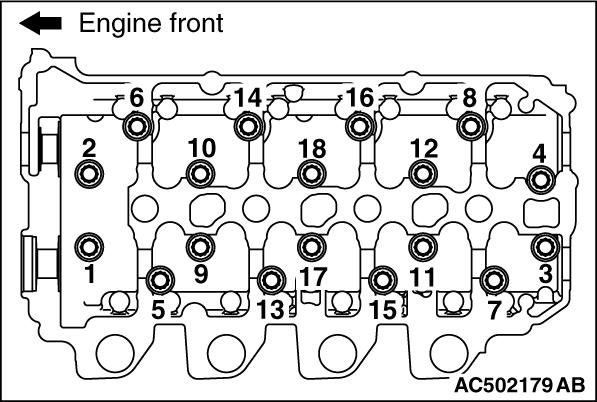
Loosen the cylinder head bolts in two or three steps in the order of the numbers shown in the illustration.
|

|
| caution |
Provide one punch mark on the head of the cylinder head bolt each time the bolt is tightened. Replace the bolt that already has five punch marks (the evidence of having been tightened five times)
|
|
|
|
1.
| caution |
Do not allow any foreign materials get into the coolant passages, oil passages and cylinder.
|
Degrease the cylinder head gasket mounting surface.
|

|
2.
| caution |
The thickness of the original cylinder head gasket is selected according to protrusion amount of the piston. Therefore, If the cylinder block, piston, connecting rod or crankshaft is replaced, the protrusion amount may be changed. Always select a correct gasket by measuring the protrusion amount. (Refer to GROUP 11B - Cylinder Head and Valves  ). ).
|
When replacing the cylinder head gasket only, confirm the gasket identification mark, and then select a replacement part according to the following table.
|
|
Specification
|
Identification mark (fitted thickness mm)
|
Part number
|
A
|
D5-205 (0.95 ± 0.04)
|
1005A205
|
B
|
D5-206 (1.00 ± 0.04)
|
1005A206
|
C
|
D5-207 (1.05 ± 0.04)
|
1005A207
|
|
|
|
|
1.
| caution |
Before installing the cylinder head bolt, check the number of punch marks on its head. (the bolt is reusable if it is four or less.) The number of punch marks corresponds to that to times the bolt has been tightened to the plastic area. If the bolt has five punch marks, replace it.
|
Set the cylinder head bolt washer with its shear droop toward the bolt head.
|
|
|
2.Apply a small amount of engine oil to the thread of the bolts and to the washers.
|


|
3.Tighten the cylinder head bolts in the following procedures.
(1)
Tighten the bolts to 78 ± 2 N·m in the order shown.
(2)
Loosen the bolts fully in the reverse sequence to that shown.
(3)
Tighten the bolts to 29 ± 2 N·m in the order shown.
(4)
Apply a paint mark to the heads of the cylinder head bolts and cylinder head, then tighten 90 degree angle as shown.
(5)
|
|
| caution |
- The bolt is not tightening sufficiently if the tightening angle is less than a 90 degree angle.
- If the tightening angle exceeds the standard specification, remove the bolt and start over from step (1).
|
|
Tighten in a 90 degree angle as shown in the instructions of the illustration, then check to see that the paint mark on the head of the cylinder head bolts and the paint mark on the cylinder head is on a linear line.
|
|
1.Use the following special tool as during removal to hold the camshaft sprocket.
- Front hub and flange yoke holder (MB990767)
- Pin (MD998719)
2.Tighten the camshaft sprocket mounting bolt to the specified torque.
Tightening torque: 88 ± 10 N·m
|
)
)
)
)
)
)
)