|
1.
| caution |
Never turn the crankshaft anti-clockwise.
|
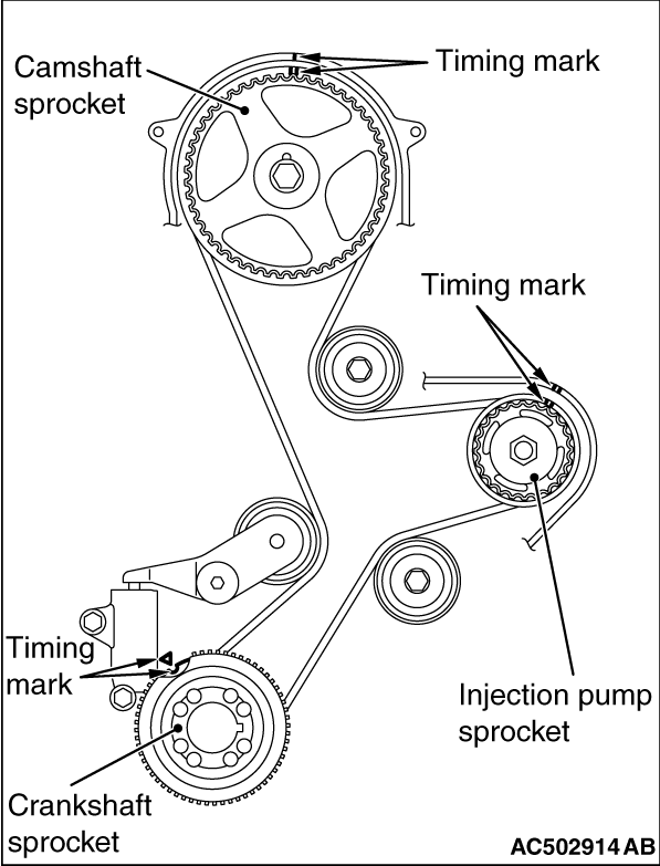
Turn the crankshaft clockwise, align each timing mark to set No.1 cylinder to TDC of its compression stroke.
|

|
2.
| caution |
To reuse the timing belt, draw an arrow indicating the rotating direction (clockwise) on the back of the belt using chalk, etc.
|
Remove the timing belt.
|

|
1.
| caution |
To reuse the timing belt B, draw an arrow indicating the rotating direction on the back of the belt using chalk, etc.
|
Loosen the timing belt B tensioner assembly mounting bolts.
2.Push the timing belt B tensioner assembly to water pump side and tighten the timing belt B tensioner assembly mounting bolts.
3.Remove the timing belt B.
|
|
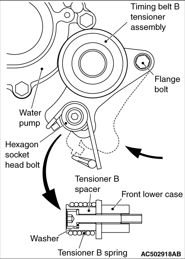
1.Install the timing belt B tensioner assembly, tensioner B spring and tensioner B spacer.
| note |
Be sure to install the tensioner B spring with its shorter end toward the water pump.
|
2.Move timing belt B tensioner assembly toward water pump and tighten mounting bolts.
|

|
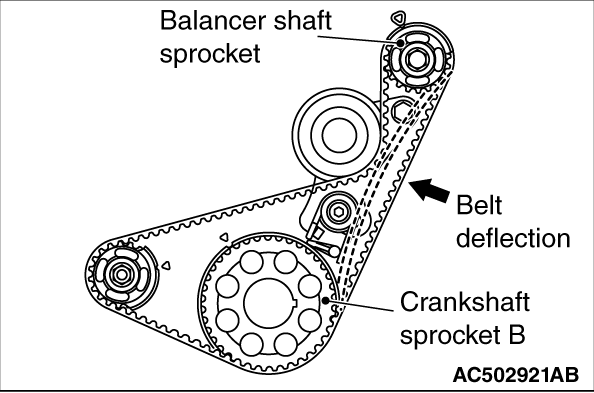
1.Align timing marks on the crankshaft sprocket B, and balancer shaft sprockets with their timing marks.
2.Install balancer timing belt B onto sprockets and ensure that its tension side is not slack.
|

|
3.Loosen timing belt B tensioner assembly mounting flange bolt, one to two turns.
4.Tighten the timing belt B tensioner assembly mounting hexagon socket head bolt.
5.timing belt B tensioner assembly mounting flange bolt.
| note |
If the bolt is tightened first, the timing belt B tensioner assembly should be turned together, resulting in reduced timing belt B tensioner assembly.
|
|
|
6.Ensure that the deflection is as specified when the timing belt B is pushed by the index finger at the position indicated by an arrow.
Belt deflection: 4 - 5 mm
|
|
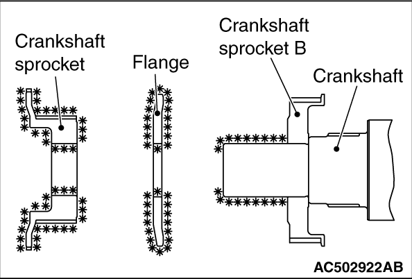
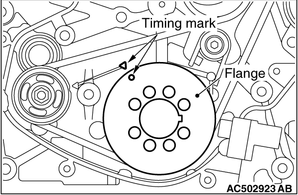
1.Clean or degrease the crankshaft, the flange and crankshaft sprocket as shown.
| note |
Also clean the degreased surfaces.
|
|
|
2.Assemble the flange by aligning the timing mark of the front lower case and the timing mark of the flange.
|


|
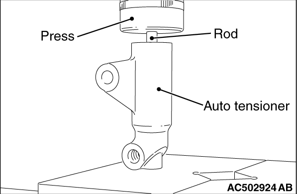
1.To reuse the auto tensioner, bleed the air according to the procedure below, and then set the rod to the auto tensioner.
(1)
|
|
| caution |
- If a horizontal press such as a vice is used, the air entrainment may occur. Thus, a vertical press must be used.
- If the compression is too fast, the procedure may damage the rod. Make sure to compress slowly and thoroughly.
- To prevent a damage to the auto tensioner, do not push down the rod exceeding the bottom end (a position where the rod protrusion is at 0.5 mm from the auto tensioner).
|
|
Set the auto tensioner to the vertical press, and then slowly compress the rod to the bottom end (a position where the rod protrusion is at 0.5 mm from the auto tensioner). Perform this operation 2 to 3 times.
(2)
With the rod protruding (a position where the rod protrusion is at 5 mm from the auto tensioner), check that there is a rigidity when the rod is pushed with a load (100 to 200 N).
(3)
If the rod rigidity is not obtained by repeating the operations of (1) and (2), replace the auto tensioner.
(4)
Compress the rod slowly, and then align the set hole A of the rod with the set hole B of the auto tensioner body.
(5)
Insert a wire or pin in the aligned set hole.
|
|
| note |
When the auto tensioner is replaced with a new part, the auto tensioner is set with a pin.
|
|
2.Install the auto tensioner in position. Leave the wire or pin installed until the auto tensioner is completely installed.
3.Install the tensioner arm assembly.
|

|
4.Align the timing mark of each sprocket.
|

|
5.In the order below, install the timing belt without slack.
| note |
When installing the timing belt into the crankshaft sprocket, slide the crankshaft sprocket to near the tip of the key, and then install the timing belt. (When installing the timing belt, be careful not to damage the belt by the cut-out of crankshaft sprocket.) After that, install the crankshaft sprocket to the correct position.
|
(1)
Crankshaft sprocket
(2)
Idler pulley
(3)
Injection pump sprocket
(4)
Idler pulley
(5)
Camshaft sprocket
(6)
Tensioner pulley
6.Check that the timing marks on sprockets are at the correct positions.
7.Remove the wire or pin of the auto tensioner.
8.Turn the crankshaft 2 turns clockwise, and then measure the protrusion of auto tensioner rod.
Standard value: 2.3 - 7.6 mm
9.Check again that the timing marks on sprockets are at the correct positions.
|
 ).
).)
)
)
)
)
)
)
)
)
)
)
)
)
)
)
)