
|
1.Use the following special tools to hold the camshaft sprocket.
- Front hub and flange yoke holder (MB990767)
- Pin (MD998719)
2.Loosen the camshaft sprocket mounting bolt and remove the camshaft sprocket.
|
|
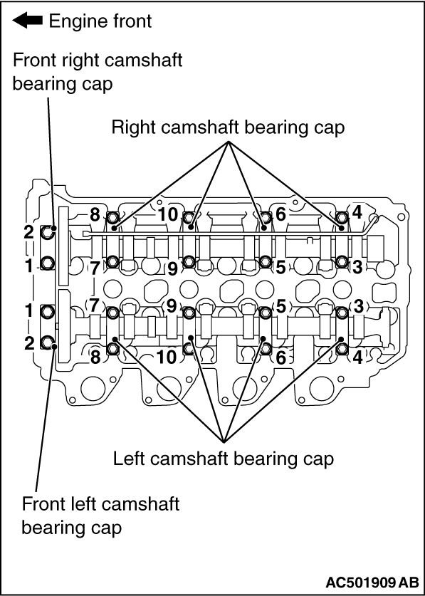
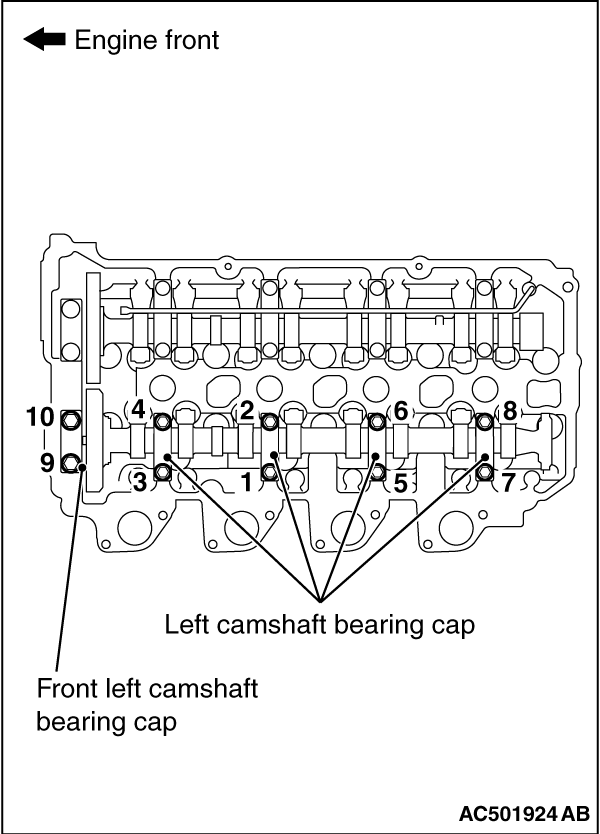
Loosen the mounting bolts of the front camshaft bearing cap and of the camshaft bearing cap in the order shown in the figure. Then, remove the front camshaft bearing cap and the camshaft bearing cap.
|
|
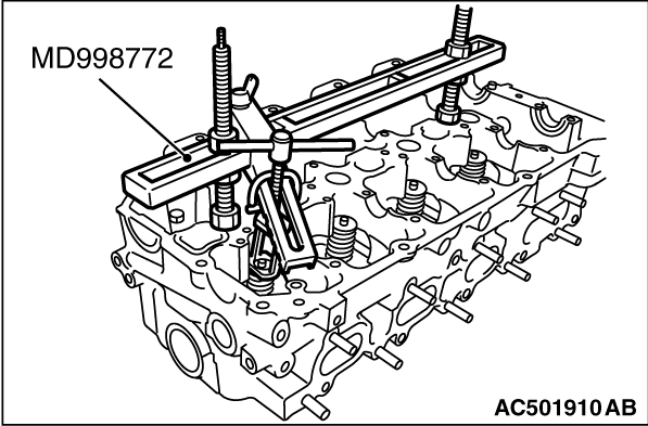
Use special tool valve spring compressor (MD998772) to compress the valve spring and then remove the valve spring retainer lock.
|
|
|
1.Apply a small amount of engine oil to the valve stem seal.
|
|
2.
| caution |
- Do not re-use the valve stem seal.
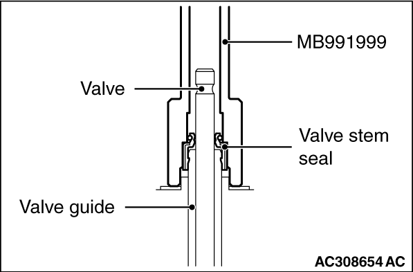
- Special tool valve stem seal installer (MB991999) must be used to install the valve stem seal. Improper installation could result in oil leaking past the valve guide.
|
Use the special tool valve stem seal installer (MB991999) to fill a new valve stem seal in the valve guide using the valve stem area as a guide.
|
|
Use special tool valve spring compressor (MD998772) to compress the valve spring and then install the valve spring retainer lock in the same manner as removal.
|
|
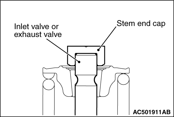
Install the stem end cap. Make sure that the stem end cap is in close contact with the stem end faces of the inlet and exhaust valve.
|

|
1.Screw the adjusting screw into the rocker arm assembly, and then temporarily assemble using a nut so that the adjusting screw protrusion becomes the dimension shown in the figure.
2.Apply the engine oil to the sliding surface of the parts below.
- Roller and valve-side sliding area of the rocker arm assembly
- Concave spherical surface of pivot bolt or spherical surface of adjusting screw
|

|
3.Place the rocker arm assembly onto the pivot bolt and the stem end cap as shown in the figure.
|
|
|
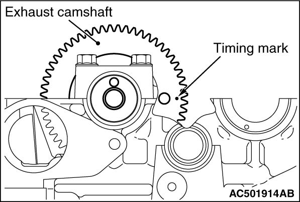
1.Apply the engine oil to the cam face, journal section, thrust face, and gear teeth face of exhaust camshaft.
|
|
2.Set the timing mark of the exhaust camshaft in the position shown in the figure.
|
|
|
1.Place the right camshaft bearing cap onto the camshaft journal section.
|
|
|
2.Apply the engine oil to the O-ring section of exhaust oil pipe assembly, and insert the tip of exhaust oil pipe assembly into the cylinder head. Then, place the pipe section onto the right camshaft bearing cap.
|

|
3.Tighten the mounting bolts of the right camshaft bearing cap and of the front right camshaft bearing cap to the specified torque in the order shown in the figure. Then, fix the right camshaft bearing cap, exhaust oil pipe assembly, and front right camshaft bearing cap to the cylinder head.
Tightening torque:
11 ± 1 N·m (Right camshaft bearing cap mounting bolts)
20 ± 1 N·m (Front right camshaft bearing cap mounting bolts)
|
|
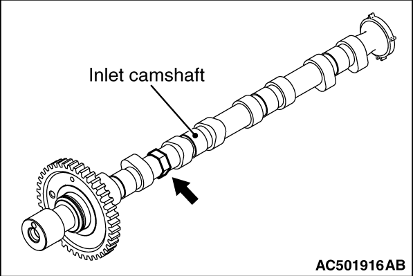
1.Fix the inlet camshaft hexagonal area using a vice or other devices.
|

|
2.Press fit the dowel pin into the inlet camshaft and sub gear so that the dimension becomes as shown in the figure.
|
|
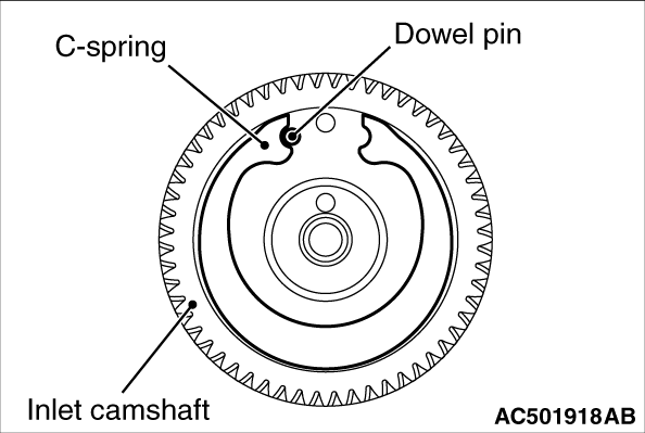
3.After contacting the C-spring with the dowel pin as shown in the figure, set to the inlet camshaft.
|

|
4.Set the sub gear to the inlet camshaft so that the sub gear dowel pin is inside the A range between the C-spring and inlet camshaft dowel pin as shown in the figure.
5.Assemble the wave washer and the snap ring to the inlet camshaft.
|

|
1.Fix the hexagonal area of inlet camshaft assembly using a vice or other devices.
|

|
2.
| caution |
Avoid turning the sub gear than necessary.
|
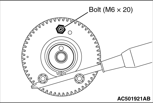
Set the flange bolts (M6 x 20) to 2 locations of sub gear. Then, using a screwdriver, turn the sub gear clockwise until the sub gear hole (M8) and the threaded hole (M6) of inlet camshaft gear match as shown in the figure.
|
|
3.Temporarily fix the sub gear using the bolt (M6 x 20). At this time, screw in until the bolt head is in contact with the sub gear.
4.Remove the 2 flange bolts (M6 x 20) installed in the step 2.
5.Remove from the vice or other devices the inlet camshaft assembly to which the sub gear being temporarily fixed. Then, apply the engine oil to the cam face, journal section, thrust face, and gear teeth face of inlet camshaft assembly.
|

|
6.Set the timing mark of the inlet camshaft assembly and exhaust camshaft in the position shown in the illustration.
|
|
|
1.Place the left camshaft bearing cap onto the camshaft journal.
|
|
|
2.Apply the engine oil to the O-ring of the inlet oil pipe assembly, and insert the tip of the inlet oil pipe assembly into the cylinder head. Then, place the pipe onto the left camshaft bearing cap.
|

|
3.Apply specified sealant to the matching area of the cylinder head assembly and the front left camshaft bearing cap as shown, and install the left camshaft bearing cap to the cylinder head assembly within 3 minutes.
Specified sealant: 3M ATD Part No.8660 or equivalent
|
|
4.Tighten the mounting bolts of the left camshaft bearing cap and of the front left camshaft bearing cap to the specified torque in the order shown in the figure. Then, fix the left camshaft bearing cap, inlet oil pipe assembly, and front left camshaft bearing cap to the cylinder head.
Tightening torque:
11 ± 1 N·m (Left camshaft bearing cap mounting bolts)
20 ± 1 N·m (Front left camshaft bearing cap mounting bolts)
5.Remove the bolt (M6 x 20) used to temporarily fix the sub gear of inlet camshaft assembly.
|
|
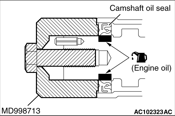
1.Apply engine oil to the entire inner diameter of the oil seal lip.
2.Use special tool camshaft oil seal installer (MD998713) to press-fit the oil seal as shown.
|
|
1.Use the following special tool as during removal to hold the camshaft sprocket.
- Front hub and flange yoke holder (MB990767)
- Pin (MD998719)
2.Tighten the camshaft sprocket mounting bolt to the specified torque.
Tightening torque: 88 ± 10 N·m
|
 ).
).)
)
)
)
)
)
)
)
)
)
)
)
)
)
)
)
)
)
)
)
)