
|
Install the stem end cap securely to attach the stem end surfaces of the intake and exhaust
valves.
|

|
Temporarily install the adjusting screw to the rocker arm with screw nut.
Protrusion: 5.5 - 6.5 mm
|
|
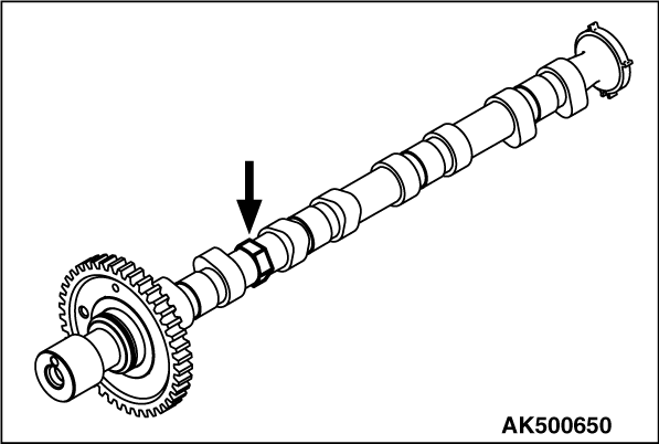
1.Fix the camshaft using the hexagonal area of the inlet camshaft.
|

|
2.Press and fit a dowel pin into the inlet camshaft and sub gear to be the dimension shown
in the illustration.
|

|
3.Place the c-spring adjoining the dowel pin which is pressed and fit into the inlet camshaft.
|

|
4.Within the area "A" between the c-spring and inlet camshaft, place the dowel pin which
is pressed and fitted into the sub gear.
5.Install the wave washer and snap ring.
|
|
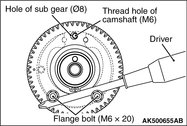
6.Set two flange bolts (M6 × 20) to two places on the sub gear. As shown in the
illustration, turn the sub gear in a clockwise direction so that the sub gear hole (Φ8)
can align with the inlet camshaft thread hole (M6).
| caution |
- Do not turn the sub gear excessively.
- Do not press the snap ring strongly with a driver.
|
7.Screw the bolts to attach the bolt heads to the sub gear. Temporarily fix the sub
gear.
8.After the temporary installation of the sub gear, remove two flange bolts (M6 × 20)
described in No. 6.
|

|
1.Install the camshaft so that each timing mark can be in position as shown in the illustration.
| note |
Carefully install the camshaft because a rocker arm assembly is easily dropped at the
camshaft installation.
|
2.Confirm all the stem end caps are installed.
3.Confirm the rocker arm assembly is straightly mounted on the pivot bolts and stem
end caps.
|

|
1.Apply specified sealant to portions indicated in illustration.
Specified sealant:
3M ATD Part No. 8660 or equivalent
|
|
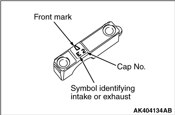
2.Installation the bearing cap.
| note |
Install the camshaft bearing cap in numerical order in accordance with "cap No." stamped
on the upper surface of the bearing cap.
|
3.Installation the O-ring and oil pipe.
|
|
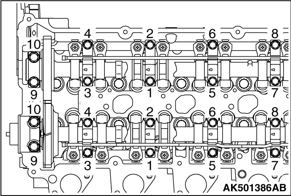
4.In accordance with the tightening order shown in the illustration, tighten the bearing
cap bolt to the specified torque.
|
|
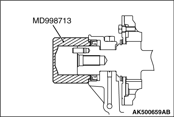
1.Apply oil to the oil seal lips.
2.Using the special tool Camshaft oil seal installer (MD998713), press-fit a new camshaft
oil seal into the front left bearing cap.
|
)

)
)
)
)
)
)
)
)
)
)
)
)