|
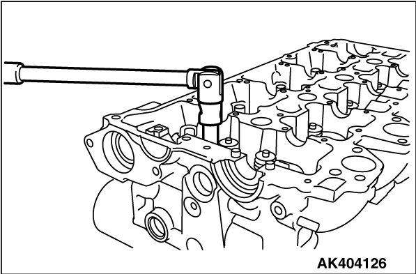
Using a 14 mm - 12 points socket wrench, loosen the cylinder head bolt. Loosen
each bolt evenly, little by little, by two or three steps.
|

|
| caution |
provide one punch mark on the head of the cylinder head bolt
each time the bolt is tightened. replace the bolt that already has five punch marks (the evidence
of having been tightened five times)
|
|
|
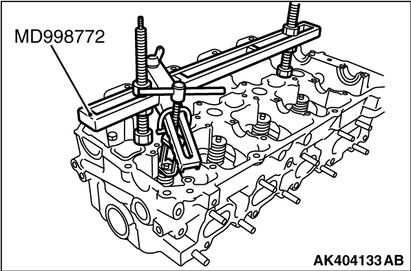
1.Set special tool Valve spring compressor (MD998772) as illustrated to compress the valve
spring. Remove the retainer lock.
2.Relieve the spring tension and remove the valve, retainer, spring, etc. Store removed
valves, springs, and other parts, tagged to indicate their cylinder no. and location for assembly.
|
|
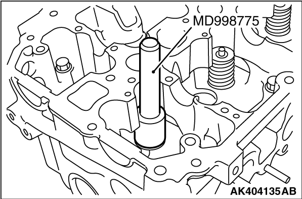
1.Install the valve spring seat.
2.The special tool Valve stem seal installer (MD998775) must be used to install the
valve stem seal. Improper installation could result in oil consumption through valve guide.
| caution |
Do not reuse removed valve stem seals.
|
|
|
| caution |
The valve spring, if excessively compressed, causes the bottom
end of the retainer to be in contact with, and damage, the stem seal.
|
Compress the valve spring using the special tool Valve spring compressor (MD998772), them
install the retainer lock.
|

|
1.In case any of the cylinder block, piston, connecting rod and crankshaft has not been
replaced, install the gasket of the same rank as before which can be identified by the identification
mark shown in the illustration at left.
|
|
2.In case any of the cylinder block, piston, connecting rod and crankshaft have been replaced,
reselect and install the gasket in accordance with the following procedure.
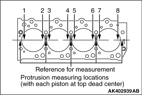
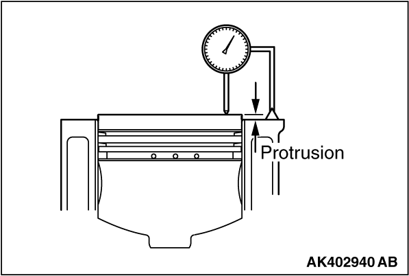
(1)
With each piston held at the top dead center, measure its protrusion from the upper
block surface at the locations shown in the illustration at left (total of eight locations).
Be sure to take measurements on the crankshaft center line.
(2)
Using the average of the eight measurements, select the gasket rank (A, B or C) in accordance
with the table given below. If, however, the maximum protrusion at any one location exceeds
the protrusion tolerance shown for any rank in the following table, use the gasket one rank
higher that rank.
Rank
|
Average value of piston protrusions mm
|
Protrusion tolerance for each rank mm
|
Thickness of selected gasket (when tightened) mm
|
Identification mark
|
A
|
0.06 - 0.12
|
0.17
|
0.95 ± 0.04
|
D5 - 205
|
B
|
0.12 - 0.18
|
0.23
|
1.00 ± 0.04
|
D5 - 206
|
C
|
0.18 - 0.24
|
-
|
1.05 ± 0.04
|
D5 - 207
|
| note |
If the piston projection exceeds the tolerance, replace the piston, connecting rod, crankshaft
or cylinder block and check again.
|
|
|
|
1.Set the cylinder head bolt washer with its shear droop toward the bolt head.
|
|
|
2.Apply engine oil to the bolt threads and washers.
|

|
3.
| note |
Using a 14 mm - 12 points socket wrench.
|
|
|
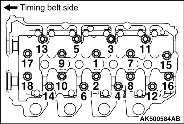
4.Tighten the bolts to 78 ± 2 N·m in the indicated sequence.
5.Loosen all the bolts completely.
6.Tighten the bolts again to a torque of 29 ± 2 N·m in the indicated
sequence. After that, confirm all bolts are reached to the specified torque, and then go to
the next process.
|
|
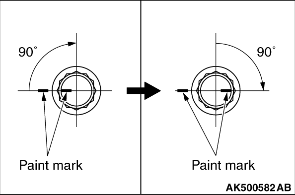
7.Make paint marks on each bolt’s head and on the cylinder head.
| caution |
- If the tightening angle
is smaller than 90°, proper fastening performance could not be assured. Be sure to
respect that angle.
- If the bolt is tightened to an angle greater than the specified angle, loosen the
bolt completely and then retighten it beginning with the first step.
|
8.Turn the bolts 90° in the tightening direction and in the indicated sequence.
9.Give another 90° turn in the tightening direction to each bolt, making sure
that the paint mark on the bolt head and that on the cylinder head are on the same line.
|
)

)
)
)
)
)
)
)
)
)
)