|
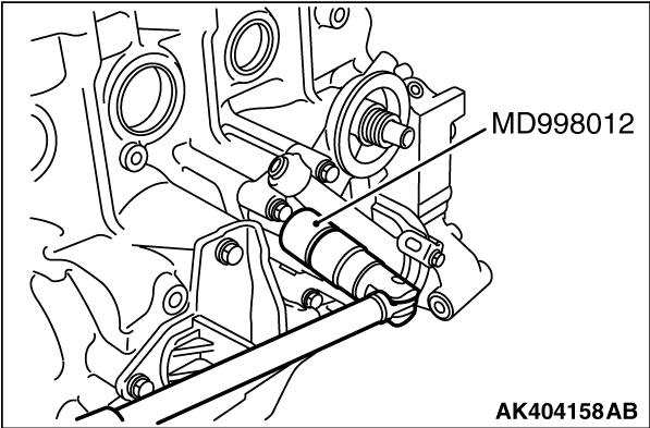
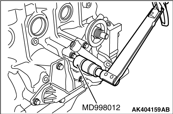
Using special tool Oil pressure switch socket wrench (MD998012), removal the oil pressure
switch.
|
|
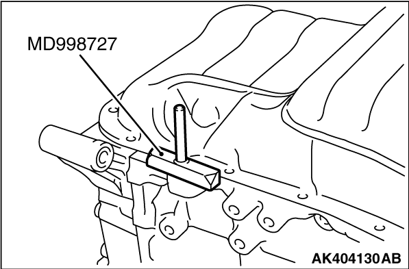
1.Knock the special tool Oil pan sealer cutter (MD998727) deeply between the oil pan and
the cylinder block.
2.Hitting the side of the special tool Oil pan sealer cutter (MD998727), slide the special
tool along the oil pan to remove it.
|
|
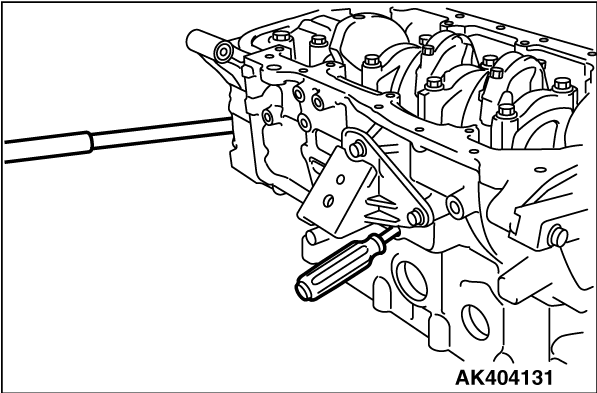
1.Remove the plug on the right side of cylinder block.
2.Insert a Phillips screwdriver into the plug hole to lock the silent shaft in position.
3.Remove the flange bolt.
|

|
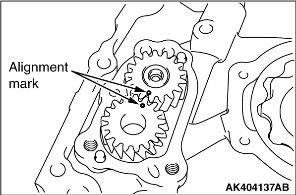
Put alignment marks on the outer and inner rotors for reference in reassembly.
|

|
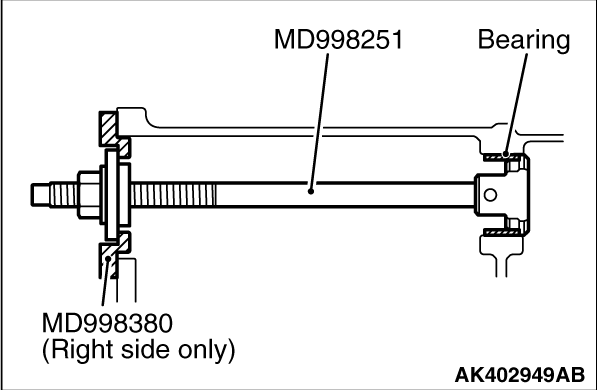
1.Install the special tool Bearing installer stopper (MD998380) to the cylinder block. This
is used to hold the special tool.
|
|
2.Pull out the rear bearing from the cylinder block using the special tool Balancer shaft
bearing puller (MD998251).
|

|
Using the special tools, press-fit the bearing into the cylinder block.
Before press-fitting the bearing, apply an ample amount of engine oil to the bearing surfaces
as well as bearing hole in the cylinder block.
- Balance shaft bearing installer (MD998250)
- Bearing installer stopper (MD998380)
|
|
|
1.Apply engine oil to the balancer shaft drive and driven gears.
|
|
2.Install the balancer shaft drive and driven gears to the front lower case. Make sure that
the alignment marks are in line.
|
|
Install the outer rotor in the same direction as before noting the mark put at the time
of removal. Apply engine oil to the entire rotor surface.
|
|
|
1.Apply engine oil to the oil seal outer surface.
|

|
2.Using the special tool Balancer shaft drive gear oil seal guide (MD998385), drive in with
a socket wrench.
|

|
1.Attach the special tool Crankshaft front oil seal guide (MD998383) to the crankshaft and
apply engine oil to the outer surface of the tool.
2.Using the special tool Crankshaft front oil seal installer (MD998382), install the
front oil seal into the front lower case.
|

|
1.Insert a Phillips screwdriver into the plug hole to block the balancer shaft.
2.Install the flange bolt and tighten to the specification.
3.Remove the screwdriver and install the plug.
|

|
Apply engine oil to the oil seal outer surface and drive in with a socket wrench.
|
|
|
Use either an oil pan gasket or a sealant for installing the oil pan. Install the oil
pan in accordance with the following procedure respectively.
|

|
1.Clean both mating surfaces of oil pan and cylinder block.
2.Apply a 4 mm wide bead of sealant to the entire circumference of the oil pan flange.
Specified sealant:
MITSUBISHI GENUINE Part No. MD970389 or equivalent
3.The oil pan should be installed in 15 minutes after the application of sealant.
<GASKET>
4.Clean both mating surfaces of oil pan and cylinder block.
|
|
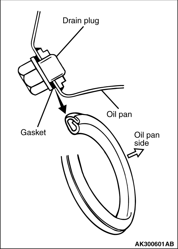
Replace the gasket with a new one and install it in the direction shown in the illustration.
|

|
Position the tab as shown in the illustration.
|

|
| caution |
This area shall be free from oil (antirust oil etc.) for switch output shall
be adversely affected
.
|
|

|
1.
| caution |
Use care not to allow the sealant to plug the oil passage.
|
Apply sealant to the threads of the switch.
Specified sealant:
3M ATD Part No. 8660 or equivalent
|
|
2.Using special tool Oil pressure switch socket wrench (MD998012), tighten the oil pressure
switch to the specified torque.
Tightening torque: 10 ± 2 N·m
|

|
1.Clean the filter mounting surface of the oil filter bracket.
2.Apply engine oil to the O-ring of the oil filter.
|
|
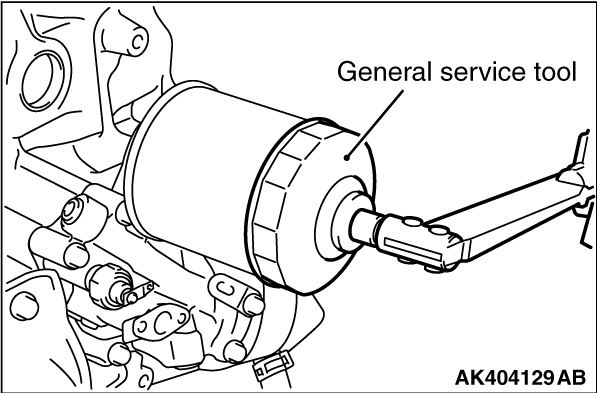
3.Using general service tool Oil filter wrench, Install the oil filter to the bracket and
tighten it to the specified torque.
Tightening torque: 22 ± 2 N·m
4.If a torque wrench cannot be used use the following procedure.
(1)
Screw in the oil filter until its o-ring contacts the oil filter bracket.
(2)
Tighten the oil filter 3/4 turn.
|
)

)
)
)
)
)
)
)
)
)
)
)
)
)
)
)
)
)
)
)
)