|
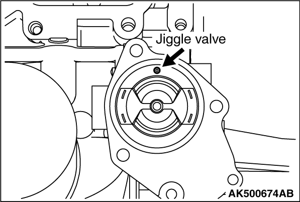
1.Check that the rubber ring is undamaged and seated correctly in the thermostat flange.
2.Install the thermostat as shown in the illustration. The jiggle valve must be at the
uppermost position.
|

|
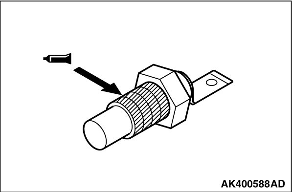
When reusing the sensor, apply the specified sealant to the threads.
Specified sealant:
3M Nut locking Part No. 4171 or equivalent
|
|
Apply the specified sealant to the threads.
Specified sealant:
3M ATD Part No. 8660 or equivalent
|

|
1.Temporarily tighten the front upper case stiffner with bolts.
2.Tighten to the specified torque of 50 ± 5 N·m Bolt "A" located at
the front upper case side.
3.Next, tighten to the specified torque of 50 ± 5 N·m Bolt "B" located
at the cylinder block side.
|
|
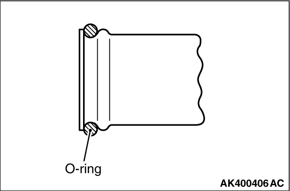
1.Attach a new O-ring to each end of the water pipe.
2.Wet the O-ring with water.
3.Insert the rear end of the pipe into the thermostat housing.
|
)

)
)
)
)
)