
|
1.As shown in the illustration, temporarily tighten to 6.0 ± 1.0 N·m the
bolts located at Side "A."
2.As shown in the illustration, tighten to the specified torque of 24 ± 3 N·m
the bolts located at Side "B" Tighten nuts to the specified torque of 20 ± 2 N·m.
3.As shown in the illustration, tighten to the specified torque of 24 ± 3 N·m
the bolts located at side "A."
|
|
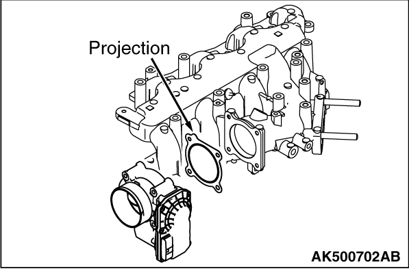
Position the projection as shown in the illustration.
|
|
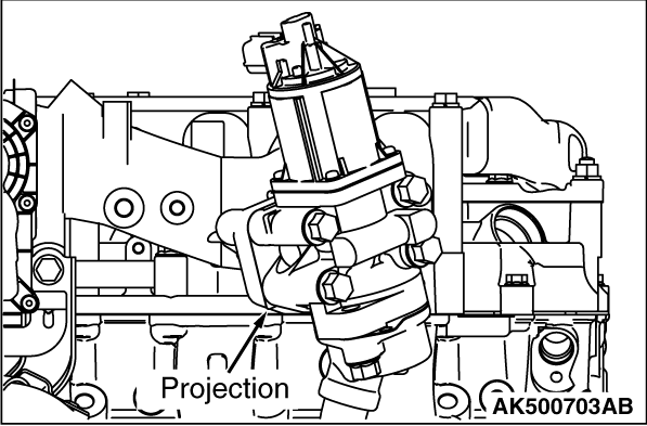
Position the projection as shown in the illustration.
|

|
Position the projection as shown in the illustration.
|
)

)
)
)
)