|
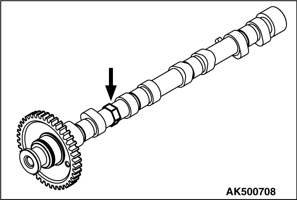
Remove the camshaft sprocket holding the hexagonal area of the camshaft with a wrench.
|
|
Tighten the camshaft sprocket to the specified torque of 88 ± 10 N·m
holding the hexagonal area of the camshaft with a wrench.
|

|
1.Apply the minimum amount of an oil to the threads and seat of the injector holder bolt.
2.Install the injector holder to the injector, and temporarily tighten it with the injector
holder bolt.
3.Install the fuel leakage pipe, and temporarily tighten it with the eyebolt and fuel
leak-off gasket.
4.Tighten to the specified torque of 15 ± 2 N·m the eyebolt located
at the injector side.
5.Tighten to the specified torque of 15 ± 2 N·m the eyebolt located
at the cylinder head side.
6.Tighten the injector holder bolt to the specified torque of 10 ± 1 N·m.
|
|
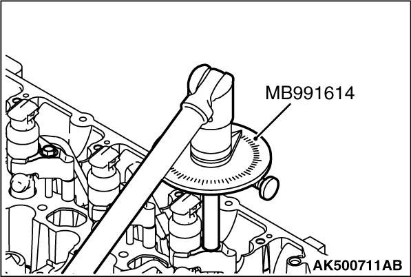
| caution |
- If the bolt is tightened
less than the specified lower limit of 120°, the bolt may become loose. Be sure to tighten
correctly.
- If the bolt is tightened in excess of the specified upper limit of 125°,
loosen the nut completely and repeat the entire procedures.
|
7.Using the special tool Angle gauge (MB991614), tighten the injector holder bolt in
the illustrated sequence by a further 120 to 125°.
|
|
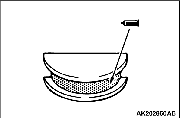
Apply specified sealant to portions indicated in illustration.
Specified sealant:
3M ATD Part No. 8660 or equivalent
|

|
1.Apply specified sealant to portions indicated in illustration.
Specified sealant:
3M ATD Part No. 8660 or equivalent
|
|
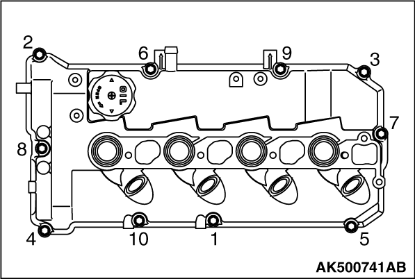
2.In accordance with the tightening order shown in the illustration, tighten bolts to 3.0 ± 1.0
N·m.
3.Again, in accordance with the tightening order shown in the illustration, tighten
bolts to the specified torque of 10 ± 2 N·m.
|

|
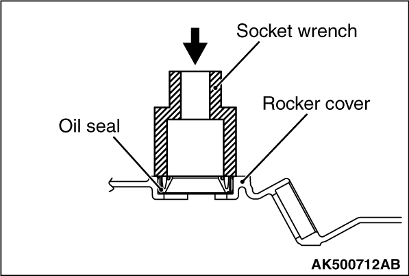
Using a proper socket wrench, the oil seal is pressed and fit into the rocker cover.
|
|
Using a proper socket wrench, the oil seal is pressed and fit into the rocker cover.
|
)

)
)
)
)
)
)
)
)