|
|
Q.
Is the check result normal?
|
|
|
 Check the speed meter (Refer to GROUP 54A -Combination Meter - On-vehicle
Service - Speedmeter Check Check the speed meter (Refer to GROUP 54A -Combination Meter - On-vehicle
Service - Speedmeter Check  ). ).
|
|
|
|
|
|
- Refer to Data list reference table .
- Item 04: Vehicle speed sensor
|
|
|
Q.
Is the check result normal?
|
|
|
 Intermittent malfunction (Refer to GROUP 00 - How to Use Troubleshooting/Inspection
Service Points - How to Cope with Intermittent Malfunctions ). Intermittent malfunction (Refer to GROUP 00 - How to Use Troubleshooting/Inspection
Service Points - How to Cope with Intermittent Malfunctions ).
|
|
|
|
|
Q.
Is the check result normal?
Go to Step 4 .
Repair or replace the connector.
|
|
| note |
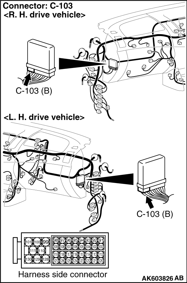
Before checking harness, check intermediate connectors C-30, C-35 <R.H. drive vehicles>,
C-53 <L.H. drive vehicles> and C-127, and repair if necessary.
|
- Check output line for open circuit and damage.
Q.
Is the check result normal?
Go to Step 5 .
Repair the damaged harness wire.
|
|
|
- Reconfirmation of diagnosis code.
|
|
|
Q.
Is the diagnosis code set?
|
|
|
Replace the engine-ECU. When the engine-ECU is replaced, write the chassis number
(Refer to GROUP 00 - How to Perform Chassis Number Writing ).
After replacing the engine-ECU, register the injector identification code and learn fuel injection
(Refer to GROUP 00 - Precautions Before Service - What The Common Rail Engine
Learns ).
|
|
|
|
|
|
Intermittent malfunction (Refer to GROUP 00 - How to Use Troubleshooting/Inspection
Service Points - How to Cope with Intermittent Malfunctions ).
|
|
|
|
)
)
)