|
|
- Ignition switch: ON
- Engine coolant temperature: 40°C or lower
|
|
|
Q.
Is the glow indicator lamp illuminates?
|

|
Q.
Are the check results normal?
 Go to Step 3 . Go to Step 3 .
 Repair or replace. Repair or replace.
|
|
- Disconnect connector, and measurement at harness side.
- Ignition switch: ON
- Voltage between terminal No. 28 and earth.
OK: System voltage
Q.
Is the check result normal?
Replace the engine-ECU. When the engine-ECU is replaced, write the chassis number
(Refer to GROUP 00 - How to Perform Chassis Number Writing  ).
After replacing the engine-ECU, register the injector identification code and learn fuel injection (Refer
to GROUP 00 - Precautions Before Service - What The Common Rail Engine Learns ). ).
After replacing the engine-ECU, register the injector identification code and learn fuel injection (Refer
to GROUP 00 - Precautions Before Service - What The Common Rail Engine Learns ).
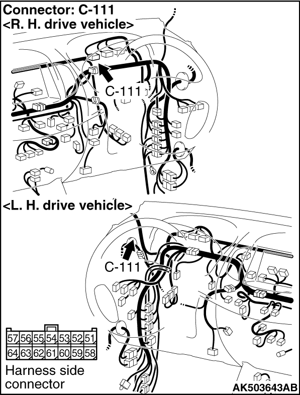
Check intermediate connector C-53 <L.H. drive vehicles> or C-35 <R.H.
drive vehicles>, and repair if necessary. If intermediate connector is normal, check and repair
harness between C-111 (terminal No. 51) combination meter connector and C-105 (terminal No. 28)
engine-ECU connector.
|

|
Q.
Are the check results normal?
Go to Step 5 .
Repair or replace.
|
|
|
- Check the glow plug relay itself (Refer to GROUP 16 - Glow System - On-vehicle
Service - Glow Plug Relay Check ).
|
|
|
Q.
Is the check result normal?
|
|
|
Replace the glow plug relay.
|
|
|
|

|
- Disconnect connector, and measurement at harness side.
- Voltage between terminal No. 1 and earth.
OK: System voltage
Q.
Is the check result normal?
Go to Step 7 .
Check harness between fusible link No. 24 and A-11 (terminal No. 1) glow plug
relay connector.
|

|
- Disconnect connector, and measurement at harness side.
- Voltage between terminal No. 1 and earth.
OK: System voltage
Q.
Is the check result normal?
Go to Step 8 .
Check harness between A-112 (terminal No. 1) glow plug relay connector and A-20X
(terminal No. 3) engine control relay connector.
|
|
|
- Check glow plug itself (Refer to GROUP 16 - Glow System - On-vehicle
Service - Glow Plug Check ).
|
|
|
Q.
Is the check result normal?
|


|
Q.
Is the check result normal?
Go to Step 10 .
Repair the harness wire.
|
|
Q.
Is the check result normal?
Go to Step 11 .
Repair or replace.
|
|
Q.
Is the check result normal?
Replace the engine-ECU. When the engine-ECU is replaced, write the chassis number
(Refer to GROUP 00 - How to Perform Chassis Number Writing ).
After replacing the engine-ECU, register the injector identification code and learn fuel injection (Refer
to GROUP 00 - Precautions Before Service - What The Common Rail Engine Learns ).
Repair the harness wire.
|
)
)
)
)
)
)
)
)