
|
Fix the fuel filter pump to a vice, and then remove the fuel filter cartridge using an oil filter wrench.
|
|
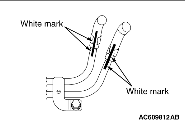
Insert each fuel return hose so that the white mark of each fuel return hose is aligned with the fuel return pipe assembly.
|
|
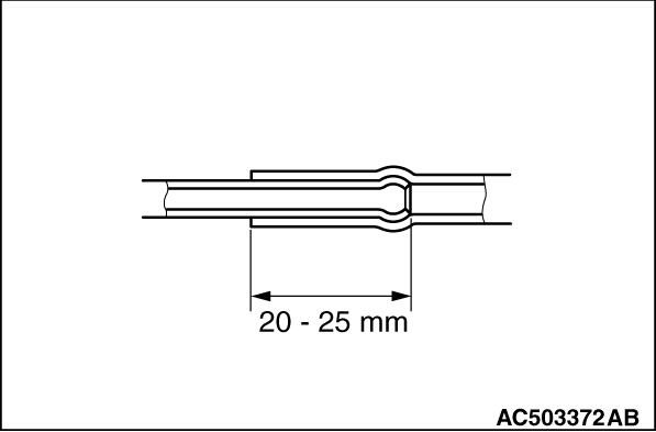
If the pipe has a stepped part, connect securely up to the stepped part. If the pipe has no stepped part, insert so that the inserted portion 20 - 25 mm long.
|
|
If the pipe has a stepped part, connect securely up to the stepped part. If the pipe has no stepped part, insert so that the inserted portion 20 - 25 mm long.
|
|
|
<Vehicles complying with emission reguration step III>
|
|
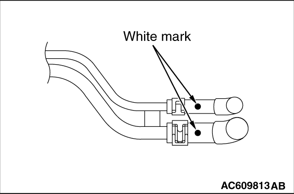
Insert the fuel hose B and fuel hose C so that the white mark of fuel hose is located as shown in the figure.
<Vehicles complying with emission reguration step IV>
|

|
Insert the fuel hose C so that the white mark of fuel hose is located as shown in the figure.
|
|
If the pipe has a stepped part, connect securely up to the stepped part. If the pipe has no stepped part, insert so that the inserted portion 20 - 25 mm long.
|
|
|
1.Clean the mounting surface on the fuel filter pump side.
|
|
|
2.Tighten the fuel filter cartridge to the specified torque from the point where the gasket contacts the mounting surface.
Tightening torque: Approximately 3/4 - 1 turn (12 ± 2 N·m)
|
)

)
)
)
)
)
)