REMOVAL AND INSTALLATION


Pre-removal and Post-installation Operation
  • Engine Coolant Draining and Refilling (Refer to ).


Removal steps


·
Under skid plate and engine room under cover (Refer to GROUP 51 - Under Cover ).


·
Air cleaner assembly (Refer to GROUP 15, Air Cleaner ).


1.
Engine cover


2.
Water pipe B


3.
Gasket


4.
Water hose


5.
Water pipe C


6.
Gasket


7.
Water hose


8.
Water hose


9.
Water hose


10.
Water pipe D


11.
Joint


12.
Heater piping hose connection

>>E<<
13.
Water pipe

>>E<<
14.
O-ring


Removal steps


·
Throttle body (Refer to GROUP 13A - Throttle Body ).


·
EGR valve and EGR cooler (Refer to GROUP 17 - EGR Valve and EGR Cooler ).


·
Inlet manifold (Refer to GROUP 15 - Inlet Manifold ).


15.
Water pipe A


16.
Water hose

>>D<<
17.
Front upper case stiffener

>>C<<
18.
Engine coolant temperature gauge unit

>>B<<
19.
Engine coolant temperature sensor
<<A>>
>>A<<
20.
Radiator upper hose connection


21.
Cooling water outlet hose fitting


22.
Cooling water outlet hose fitting gasket

REMOVAL SERVICE POINT


<<A>> RADIATOR UPPER HOSE DISCONNECTION


Make mating marks on the radiator hose and the hose clamp. Disconnect the radiator hose.

INSTALLATION SERVICE POINTS


>>A<< RADIATOR UPPER HOSE CONNECTION


1.Insert radiator hose as far as the projection of the cooling water outlet hose fitting.
2.Align the mating marks on the radiator hose and hose clamp, and then connect the radiator hose.

>>B<< ENGINE COOLANT TEMPERATURE SENSOR INSTALLATION


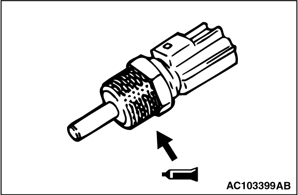
Apply the specified sealant to the thread of the engine coolant temperature sensor, and then tighten it to the specified torque.

    Specified Sealant: 3M Nut Locking Part No.4171 or equivalent
    Tightening torque: 29 ± 10 N·m

>>C<< ENGINE COOLANT TEMPERATURE GAUGE UNIT INSTALLATION


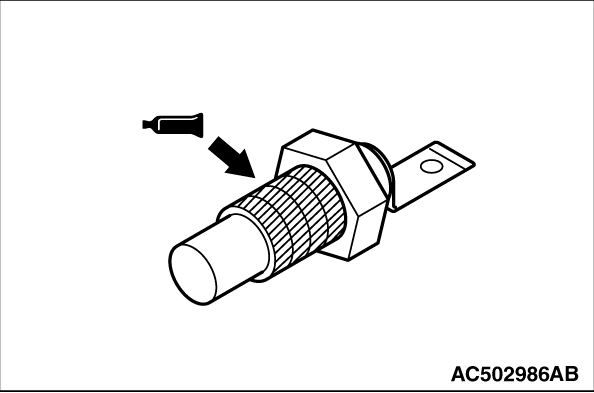
Apply the specified sealant to the thread of the engine coolant temperature gauge unit, and then tighten it to the specified torque.

    Specified Sealant: 3M ATD Part No. 8660 or equivalent
    Tightening torque: 11 ± 1 N·m

>>D<< FRONT UPPER CASE STIFFENER INSTALLATION


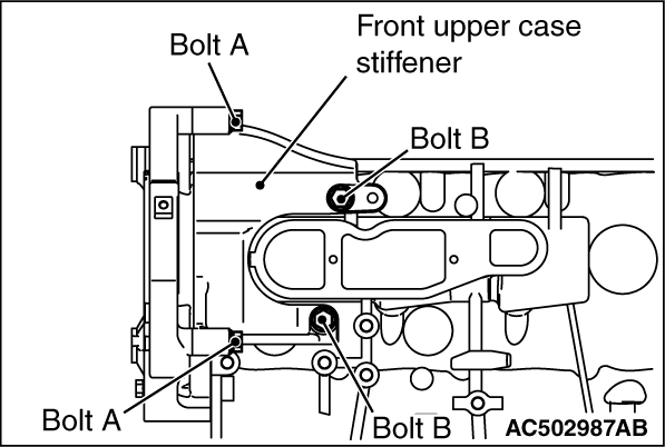
1.Temporarily tighten the front upper case stiffener with bolts.
2.Tighten the bolt A located at the front upper case side to the specified torque.
Tightening torque: 50 ± 5 N·m
3.Next, tighten the bolt B located at the cylinder block side to the specified torque.
Tightening torque: 50 ± 5 N·m

>>E<< O-RING/WATER PIPE INSTALLATION


caution Do not allow engine oil or other grease to adhere to the cooling water line O-ring

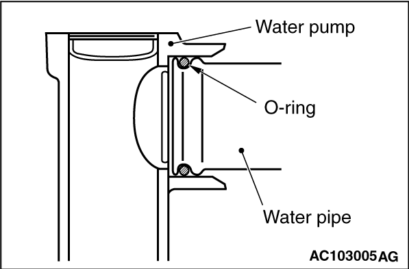
Fit the O-ring to the groove in the water pipe. Then lubricate the rim of O-ring or the inside of water pipe fixing position with water, and then insert the water pipe to the water pump.