|
|
1.Remove the spring pin <V5MB1-J-NE, NEG>.
|
|
|
2.Remove the transfer and the gear change shifter <V5MB1-J-NE, NEG>.
|
|
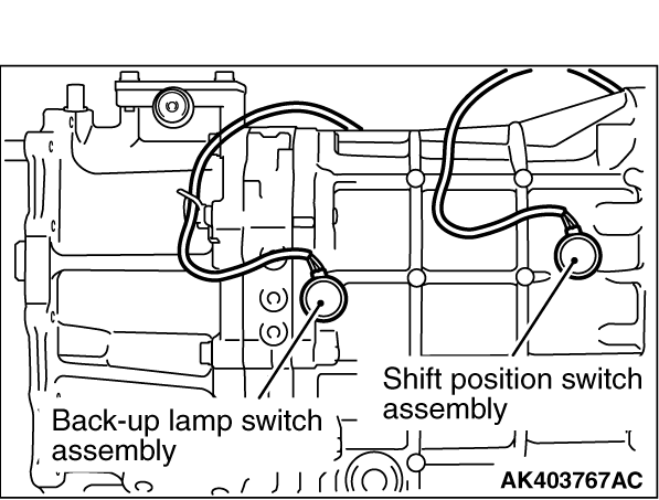
3.Remove the shift position switch assembly and the back-up lamp switch assembly.
|

|
4.Remove the clutch housing.
|

|
5.Remove the vehicle speed sensor <R5MB1-J-NC>.
|
|
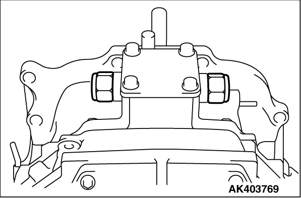
6.Remove the reverse restrict pin assembly <V5MB1-J-NE, NEG> (2 places).
|
|
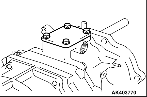
7.Remove the cover <V5MB1-J-NE, NEG>.
|
|
8.Remove the flange bolt <V5MB1-J-NE, NEG>.
|
|
9.Remove the control shaft assembly <V5MB1-J-NE, NEG>.
|

|
10. Remove the shift lever housing <V5MB1-J-NE, NEG>.
|
|
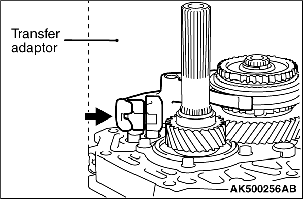
11.Remove the transfer adaptor sub-assembly <V5MB1-J-NE, NEG> and the wiring harness
clamp bracket (3 places).
12.Remove the extension housing sub-assembly <R5MB1-J-NC>.
|

|
13.Remove the oil receiver pipe.
|

|
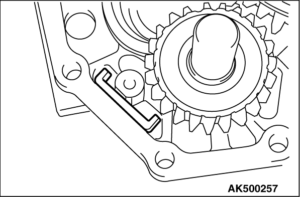
14.Remove the straight screw plug with head.
|

|
15.Remove the slotted spring pin.
|

|
16.Remove the reverse restrict pin assembly.
|

|
17.Remove the wiring harness clamp bracket <V5MB1-J-NE, NEG>.
|

|
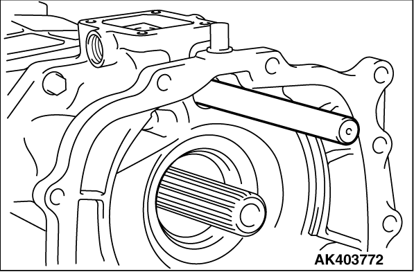
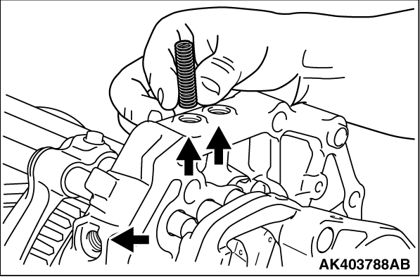
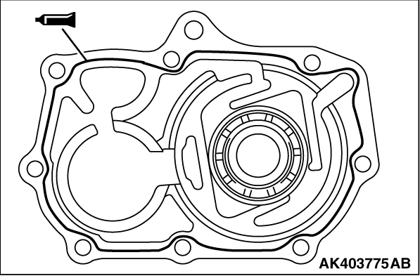
18.Remove the front bearing retainer.
|
|
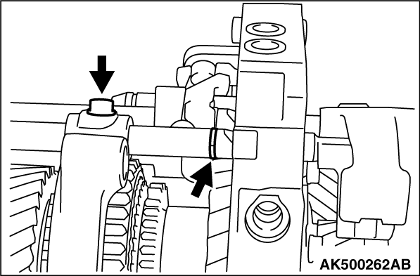
20.Remove the shaft snap ring.
|
|
21.Remove the shaft snap ring.
|

|
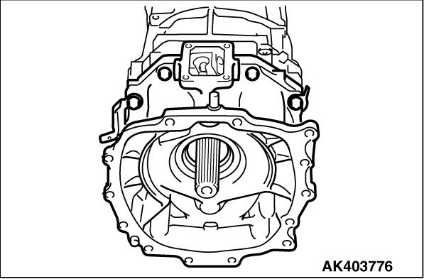
22.Remove the transmission case sub-assembly.
|
|
23.Remove the transmission magnet.
|

|
24.Remove the straight screw plug with head (3 places).
|
|
25.Remove the compression spring (3 places).
|

|
26.Remove the ball (3 places).
|

|
27.Remove the shaft snap ring of the gear shift fork shaft No.2 and the washer based hexagon
bolt of the gearshift fork No.2.
|

|
28.Remove the gear shift fork shaft No.2.
|

|
29.Remove the gear shift fork No.2.
|
|
31.Remove the shaft snap ring of the gear shift fork shaft No.1 and the washer based hexagon
bolt of the gear shift fork No.1.
|

|
32.Remove the gear shift fork shaft No.1.
|

|
33.Remove the straight pin of the gear shift fork shaft No.1.
|

|
35.Remove the gear shift fork No.1.
|

|
36.Remove the shaft snap ring of the gear shift fork shaft No.3.
|

|
37.Remove the slotted spring pin of the gear shift fork No.3 assembly.
|

|
38.Remove the gear shift fork No.3 assembly and the gear shift fork shaft No.3.
|

|
41.Remove the shaft snap ring of the gear shift fork shaft No.4.
|


|
42.Remove the gear shift fork shaft No.4.
|

|
44.Remove the compression spring.
|
|
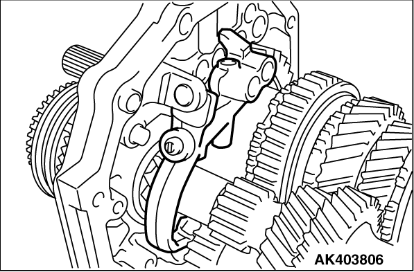
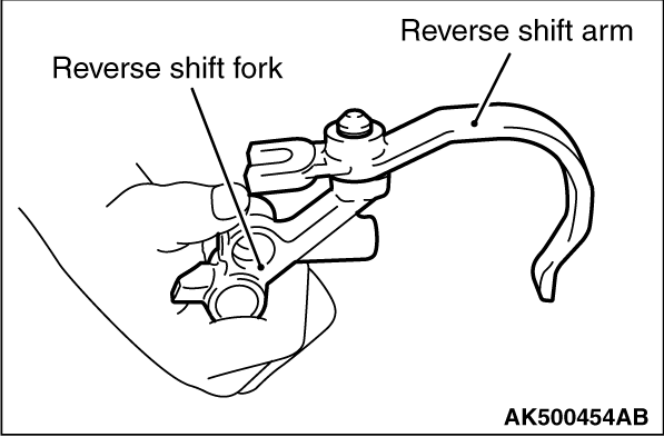
45.Remove the reverse shift fork and the reverse shift arm.
|
|
47.Remove the reverse shift arm.
|
|
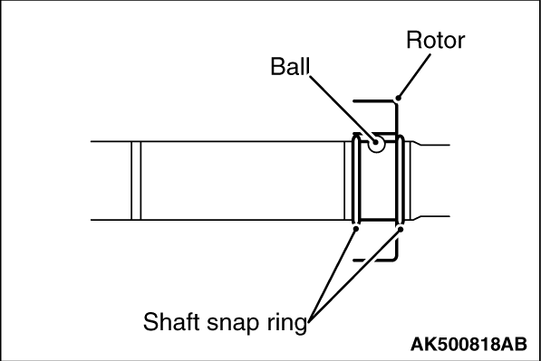
48.Remove the shaft snap ring <R5MB1-J-NC> (2 places).
49.Remove the rotor <R5MB1-J-NC>.
50.Remove the ball <R5MB1-J-NC>.
|

|
51.Remove the shaft snap ring.
|

|
52.Remove the transmission hub sleeve No.3.
|

|
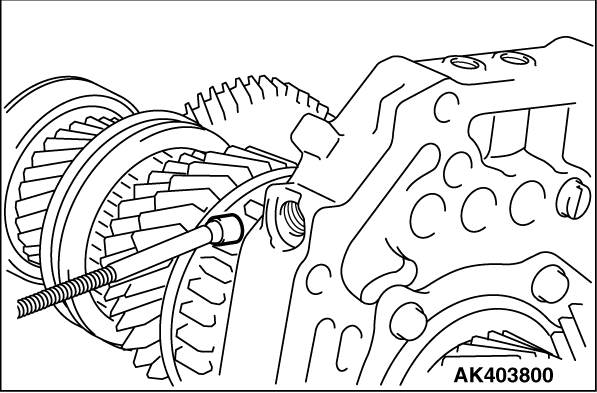
53.Use special tools to remove the gear spline piece No.5.
- Steering wheel puller (MB990803)
- Side bearing puller cup (MB990811)
|

|
54.Remove the synchronizer outer race No.3.
|

|
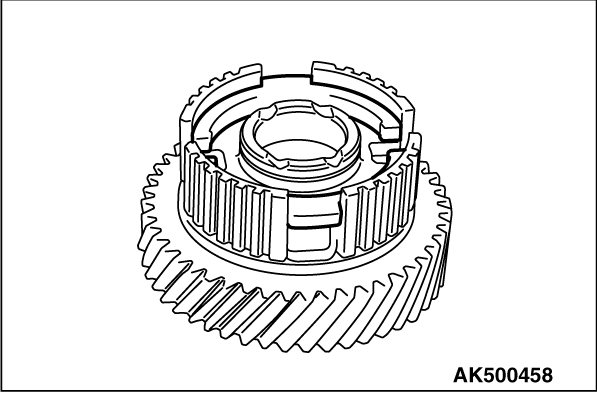
55.Remove the counter shaft gear No.5.
|
|
56.Remove the shaft snap ring.
|

|
57.Remove the synchromesh shifting key spring No.3.
|
|
58.Remove the synchromesh shifting key spring No.3.
|
|
59.Remove the synchromesh shifting key No.3.
|
|
60.Remove the needle roller bearing.
|

|
61.Remove the 5th gear thrust washer.
|

|
62.Remove the straight pin.
|

|
63.Remove the rear bearing output shaft retainer.
|

|
65.Remove the reverse idler gear shaft and reverse idler gear sub-assembly.
|
|
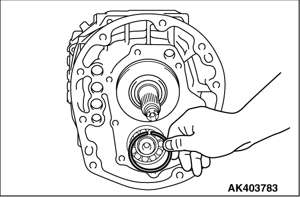
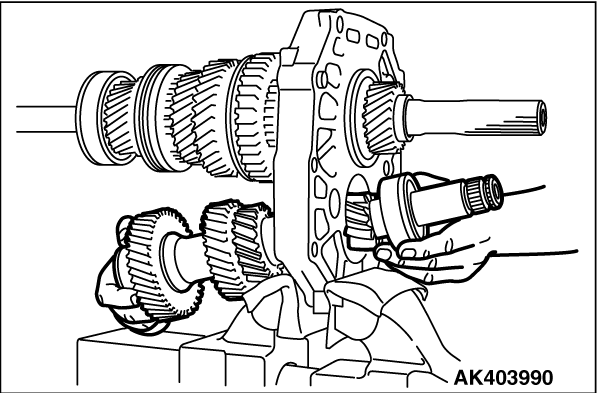
66.Remove the counter gear sub-assembly and cylindrical roller bearing.
|

|
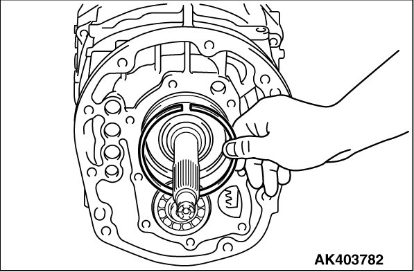
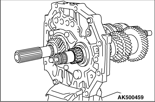
67.Remove the input shaft sub-assembly.
|
|
68.Remove the output shaft sub-assembly.
|

|
69.Remove the reverse shift arm bracket.
|
|
1.Set the reverse shift arm bracket to the intermediate plate and tighten the bolts to the
specified torque of 18 ± 5 N·m.
|
|
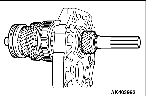
2.Install the output shaft sub-assembly to the intermediate plate.
|
|
3.Install the input shaft sub-assembly to the output shaft sub-assembly.
|

|
4.Insert the counter gear sub-assembly into the intermediate plate and hold it. Insert the
cylindrical roller bearing into the intermediate plate and the counter gear sub-assembly.
|
|
5.Install the reverse idler gear shaft and reverse idler gear sub-assembly to the intermediate
plate.
|

|
6.Install the shaft snap ring to the radial ball bearing of the input shaft sub-assembly.
|

|
7.Set the rear bearing output shaft retainer and tighten the bolts to the specified torque
of 18 ± 5 N·m.
| note |
Fit the rear bearing output shaft retainer into the reverse idler gear shaft slot.
|
|
|
8.Install the straight pin.
|

|
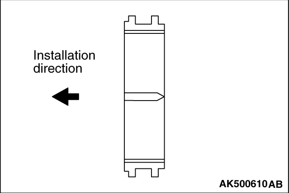
9.Check the installation direction of 5th gear thrust washer, and install it.
|
|
10.Install the needle roller bearing.
|
|
11.Install the synchromesh shifting key No.3 to the counter shaft gear No.5.
|
|
12.Install the synchromesh shifting key spring No.3 to the counter shaft gear No.5.
|
|
13.Install the synchromesh shifting key spring No.3 to the counter shaft gear No.5.
|
|
14.Install the shaft snap ring to the counter shaft gear No.5.
|
|
15.Install the counter shaft gear No.5.
|

|
16.
| caution |
Fit the protrusions of synchronizer ring between keys.
|
Install the synchronizer outer race No.3.
|

|
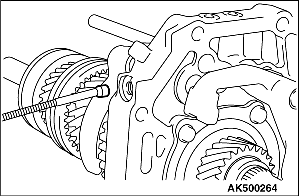
17.Using special tools to install the gear spline piece No.5.
- Installer cap (MD998812)
- Installer-100 (MD998813)
- Installer adapter (56) (MD998827)
|
|
18.Check the installation direction of the transmission hub sleeve No.3 and install it on
the counter shaft.
| note |
After installation, check the sleeve operate smoothly.
|
|
|
19.Select a snap ring to secure the thrust clearance. Install it into the counter gear sub-assembly.
Standard value: 0 - 0.1 mm
|
|
20.Install the ball to the rotor <R5MB1-J-NC>.
21.Install the rotor to the output shaft <R5MB1-J-NC>.
22.Remove the shaft snap ring to the output shaft <R5MB1-J-NC> (2 places).
|
|
23.Install the reverse shift arm to the reverse shift fork.
|
|
25.Install the reverse shift fork and the reverse shift arm to the intermediate plate.
|
|
26.Install the compression spring into the reverse shift fork.
|

|
27.Install the ball into the reverse shift fork.
|
|
28.
| caution |
Install the gear shift fork shaft No.4 carefully in the specified direction.
If the installation direction is wrong, the roller would be in the shaft concave and the gearshift
fork shaft No.4 would not be installed.
|
Install the gear shift fork shaft No.4 into the intermediate plate and the reverse shift
fork.
|
|
29.Install the shaft snap ring into the gear shift fork shaft No.4.
|

|
30.Install the ball into the reverse shift fork.
|
|
31.Install the roller A to the intermediate plate.
|
|
32.Install the gear shift fork No.3 assembly on the transmission hub sleeve No.3 and hold
it. Insert the gear shift fork shaft No.3 into the gear shift fork No.3 assembly, the intermediate
plate and the reverse shift fork.
|

|
33.Install the slotted spring pin to the gear shift fork No.3 assembly.
|
|
34.Install the snap ring to the gear shift fork shaft No.3.
|
|
35.Install the gear shift fork No.1 on the reverse gear.
|
|
36.Install the roller A to the intermediate plate.
|
|
37.Install the straight pin to the gear shift fork shaft No.1.
|
|
38.Install the gear shift fork shaft No.1 to the intermediate plate and the gear shift fork
No.1.
|
|
39.Install the shaft snap ring to the gear shift fork shaft No.1. Tighten the washer based
hexagon bolt to the specified torque of 19.5 ± 3.9 N·m.
|

|
40.Install the roller A to the intermediate plate.
|
|
41.Install the gear shift fork No.2 on the transmission hub sleeve No.2.
|
|
42.Install the gear shift fork shaft No.2 to the intermediate plate, the gear shift fork
No.1 and the gear shift fork No.2.
|
|
43.Install the shaft snap ring to the gear shift fork shaft No.2. Tighten the washer based
hexagon bolt to the specified torque of 19.5 ± 3.9 N·m.
|
|
44.Install the ball to the intermediate plate (3 places).
|
|
45.Install the compression spring to the intermediate plate (3 places).
|
|
46.Apply sealant to the threads. Tighten the straight screw plug with head to the specified
torque of 18.5 ± 5.5 N·m (3 places).
Special sealant:
Mitsubishi genuine sealant Part No. MD994421 or equivalent
| note |
The new bolt does not require sealant application as it is precoated with sealant.
|
|
|
47.Install the transmission magnet to the intermediate plate.
|
|
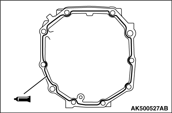
48.Apply a 1.2 mm diameter bead of liquid gasket to the intermediate plate mounting surface
of the transmission case sub-assembly.
Special sealant:
Mitsubishi genuine sealant Part No. MD994421 or equivalent
|
|
49.Install the transmission case sub-assembly to the intermediate plate.
|
|
50.Install the snap ring to the cylindrical roller bearing.
|
|
51.Install the snap ring to the radial ball bearing.
|

|
52.Using special tool install the oil seal to the front bearing retainer.
- Installer adapter (MB990929)
- Installer bar (MB990938)
|
|
53.Apply a 1.2 mm diameter bead of liquid gasket to the transmission case sub-assembly mounting
surface of the front bearing retainer sub-assembly with seal.
Special sealant:
Mitsubishi genuine sealant Part No. MD994421 or equivalent
|
|
54.
| caution |
Do not damage to the oil seal lip during the installation.
|
Apply sealant to the threads. Install the front bearing retainer to the transmission case
sub-assembly and tighten the bolts to the specified torque of 16.5 ± 5.0 N·m.
Special sealant:
Mitsubishi genuine sealant Part No. MD994421 or equivalent
| note |
The new bolt does not require sealant application as it is precoated with sealant.
|
|
|
55.Install the wiring harness clamp bracket <V5MB1-J-NE, NEG> to the transmission case
sub-assembly and tighten the bolt to the specified torque of 18 ± 3 N·m.
|
|
56.Install the reverse restrict pin assembly to the transfer adaptor sub-assembly.
|
|
57.Install the slotted spring pin to the reverse restrict pin assembly.
|
|
58.Apply sealant to the threads. Tighten the straight screw plug with head to the specified
torque of 18.5 ± 5.5 N·m.
Special sealant:
Mitsubishi genuine sealant Part No. MD994421 or equivalent
| note |
The new bolt does not require sealant application as it is precoated with sealant.
|
|
|
59.Install the oil receiver pipe into the transfer adaptor sub-assembly <V5MB1-J-NE,
NEG> and extension housing sub-assmbly <R5MB1-J-NC>.
|
|
60.Apply a 1.2 mm diameter bead of liquid gasket to the intermediate plate mounting surface
of the transfer adaptor sub-assembly <V5MB1-J-NE, NEG> and extension housing sub-assembly <R5MB1-J-NC>.
Special sealant:
Mitsubishi genuine sealant Part No. MD994421 or equivalent
|
|
61.Install the transfer adaptor sub-assembly <V5MB1-J-NE, NEG>. Install the wiring harness
clamp bracket (3 places) and tighten the bolts to the specified torque of 37 ± 11 N·m.
62.Install the extension housing sub-assembly <R5MB1-J-NC>. Install the wiring harness
clamp bracket (3 places) and tighten the bolts to the specified torque of 37 ± 11 N·m.
|
|
63.
| caution |
When installing the shift lever housing, securely fit the shift lever
housing into the head of the fork shaft.
|
Install the shift lever housing <V5MB1-J-NE, NEG> to the transfer adaptor sub-assembly.
|
|
64.Install the control shaft assembly <V5MB1-J-NE, NEG> to the transfer adaptor sub-assembly
and the shift lever housing.
|
|
65.Tighten the flange bolt <V5MB1-J-NE, NEG> to the specified torque of 33 ± 3
N·m.
|

|
66.Apply a 1.2 mm diameter bead of liquid gasket to the case mounting surface of the transfer
adaptor sub-assembly.
Special sealant:
Mitsubishi genuine sealant Part No. MD994421 or equivalent
|
|
67.Install the cover <V5MB1-J-NE, NEG> to the transfer adaptor sub-assembly and tighten
the bolt with washer to the specified torque of 18 ± 5 N·m.
|
|
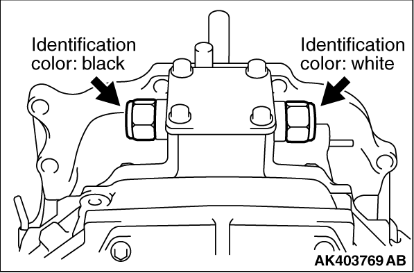
68.
| caution |
Install the reverse restrict pin assembly carefully in the accordance
with the identification color as shown in the illustration.
|
Tighten the reverse restrict pin assembly <V5MB1-J-NE, NEG> to the specified torque
of 37 ± 11 N·m (2 places).
|

|
69.Install the vehicle speed sensor <R5MB1-J-NC> and tighten the bolts to the specified
torque of 11 ± 1 N·m.
|
|
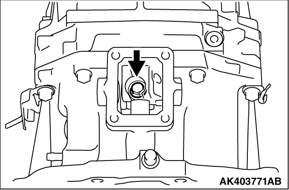
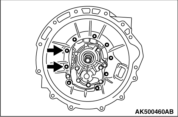
70.
| caution |
Install the bolt and washer (with sealant) to the position having the
arrow as shown in the illustration.
|
Install the clutch housing into the transmission case sub-assembly. Tighten the bolt with
washer to the specified torque of 36 ± 7 N·m (7 places). Tighten the bolt
with washer (with sealant) to the specified torque of 34 ± 6 N·m (2 places).
Special sealant:
Mitsubishi genuine sealantPart No. MD994421 or equivalent
|
|
71.Tighten the shift position switch assembly and the back-up lamp switch assembly to the
specified torque of 44 ± 9 N·m.
72.Install the transfer and the gear change shifter <V5MB1-J-NE, NEG>. Tighten the
bolts to the specified torque of 35 ± 6 N·m.
73.Install the spring pin <V5MB1-J-NE, NEG>.
|
)
)
)
)
)
)
)
)
)
)
)
)
)
)
)
)
)
)
)
)
)
)
)
)
)
)
)
)
)
)
)
)
)
)
)
)
)
)
)
)
)
)
)
)
)
)
)
)
)
)
)
)
)
)
)
)
)
)
)
)
)
)
)
)
)
)
)
)
)
)
)
)
)
)
)
)
)
)
)
)
)
)
)
)
)
)
)
)