|
|
Item 34: Inhibitor switch  (Refer to data list reference
table). (Refer to data list reference
table).
|
|
|
Q.
Is the check result normal?
|
|
|
 Intermittent malfunction (Refer to GROUP 00 -
How to Cope with Intermittent
Malfunction ). Intermittent malfunction (Refer to GROUP 00 -
How to Cope with Intermittent
Malfunction ).
|
|
|
|
|
|
NO <none of the selector lever positions are displayed on M.U.T.-III> : Go to Step 2. : Go to Step 2.
|
|
|
|
|
|
NO <only one of the selector lever positions is not displayed on M.U.T.-III> : Go to Step 6.
|
|
|
|
|
|
Q.
Is the check result normal?
|
|
|
 Replace the inhibitor switch. Replace the inhibitor switch.
|
|
|
|

|
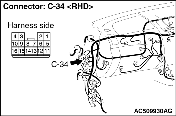
Check for the contact with terminals.
Q.
Is the check result normal?
Go to Step 4.
Repair the defective connector.
|
|
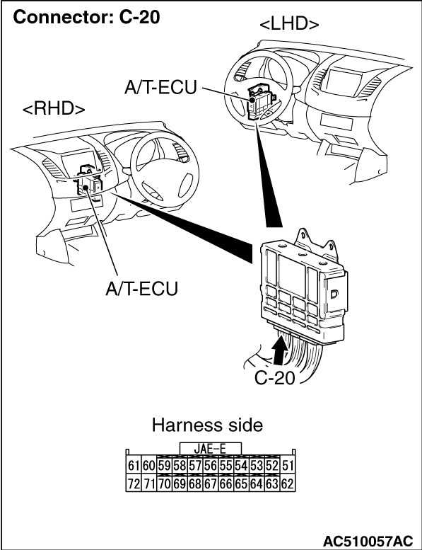
Check the power supply line for open circuit.
Q.
Is the check result normal?
Go to Step 5.
Repair the wiring harness.
|
|
|
Item 34: Inhibitor switch (Refer to data list reference
table).
|
|
|
Q.
Is the check result normal?
|
|
|
Intermittent malfunction (Refer to GROUP 00 -
How to Cope with Intermittent
Malfunction ).
|
|
|
|
|
|
Q.
Is the check result normal?
|
|
|
Replace the inhibitor switch.
|
|
|
|
|
Check for the contact with terminals.
Q.
Is the check result normal?
Go to Step 8.
Repair the defective connector.
|
|
Check the output line for open circuit.
Q.
Is the check result normal?
Go to Step 5.
Repair the wiring harness.
|
)
)
)
)
)
)
)
)