
|
1.Set special tools as shown in the illustration.
- Spring compressor (MD999590)
- Spring compressor retainer (MD998924)
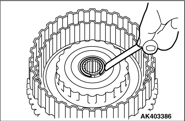
2.Compress the return spring, and remove the snap ring.
|
|
|
1.Apply ATF to the D-ring.
|
|
|
2.Install the D-ring in the reverse clutch retainer, piston, overdrive clutch piston
and spring retainer grooves. Make sure that the D-ring is not twisted or damaged when installing.
|

|
Align the reverse clutch piston and reverse clutch retainer holes (A and B), and then
assemble.
|

|
Align the two return spring holes with the two projections on the override clutch piston,
and then assemble.
|
|
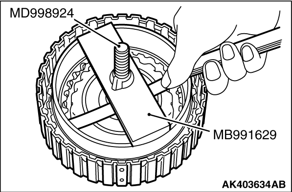
1.Set special tools as shown in the illustration.
- Spring compressor (MD999590)
- Spring compressor retainer (MD998924)
2.Tighten the special tool nut, and press the spring retainer against the reverse clutch
retainer.
3.Install the thickest snap ring that can be fitted in the snap ring groove of reverse
clutch retainer.
|
|
4.Check the clearance between the snap ring and spring retainer. If the clearance is not
within the standard value range, make adjustment by selecting a snap ring of an appropriate
thickness.
Standard value: 0 - 0.09 mm
|

|
1.Alternately assemble the clutch disc and clutch plate in the reverse clutch piston.
2.Install the reaction plate so that it is oriented as shown in the illustration.
|
|
|
1.Install the snap ring in the reverse clutch piston groove.
|
|
2.Set special tools as shown in the illustration, and compress the clutch element
- Spring compressor (MB991629)
- Spring compressor retainer (MD998924)
|

|
3.Check the clearance (overdrive clutch end play) of the snap ring and reaction plate is
the standard value. If the clearance is not at the standard value, select the snap ring and
adjust so that the clearance is within the standard value.
Standard value: 2.0 - 2.2 mm
|
|
1.
| caution |
Soak the clutch discs in AFT before installing them.
|
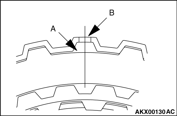
Alternately assemble the clutch plate and clutch disc in the reverse clutch retainer.
Align and assemble both clutch plates (where there are no teeth) (A in the illustration) with the
reverse clutch retainer hole (B in the illustration).
|

|
2.Install the reaction plate so that it is oriented as shown in the illustration. Assemble
in the same manner as the clutch plate so the section with no teeth (A in the illustration) matches
the retainer hole (B in the illustration).
|
|
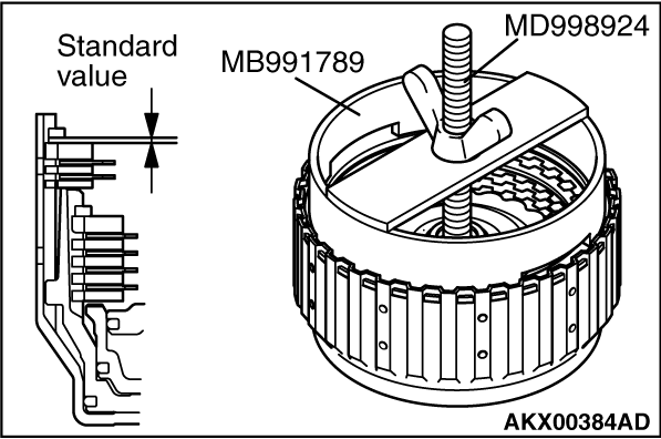
1.Install the snap ring in the reverse clutch retainer groove.
2.Set special tools as shown in the illustration, and compress the clutch element.
- Spring compressor (MB991789)
- Spring compressor retainer (MD998924)
3.Check that the clearance between the snap ring and the clutch reaction plate is within
the standard valus.if not within the standard value, select a snap ring to adjust.
Standard value: 1.5 - 1.7 mm
|
)

)
)
)
)
)
)
)
)
)
)