|
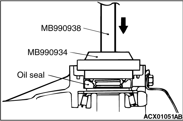
Use the following special tools to insert the oil seal, and then apply a thin coat of multipurpose grease to the lip of the oil seal.
- Bar (MB990938)
- Installer adapter (MB990934)
|

|
Use the following special tools to press-fit the drive pinion rear bearing outer races into the gear carrier.
- Bar (MB990938)
- Installer adapter (MB990936)
|

|
Use the following special tools to press-fit the drive pinion rear bearing outer races into the gear carrier.
- Bar (MB990938)
- Installer adapter (MB990934)
|
|
|
Adjust the drive pinion height as follows:
|
|
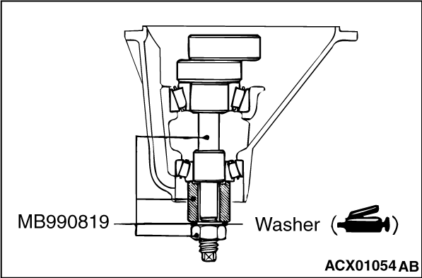
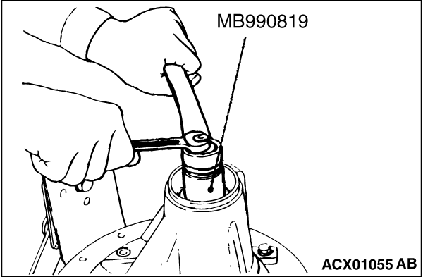
1.Apply multipurpose grease to the washer of special tool drive pinion gauge assembly (MB990819).
2.Install special tool, drive pinion front and rear bearing inner races to the gear carrier.
|
|
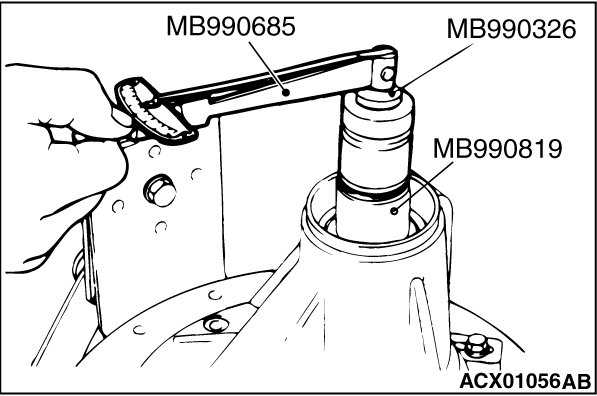
3.
| caution |
There should be no gear oil adhered to the bearing.
|
Tighten the nut of special tool while measuring the turning torque of the drive pinion by using the following special tools. Gradually keep tightening the nut of special tool until the turning torque of the drive pinion (without oil seal) is at the standard value.
- Preload socket (MB990326)
- Torque wrench (MB990685)
- Drive pinion gauge assembly (MB990819)
Standard value:
|
|
Bearing division
|
Bearing lubrication
|
Turning torque
|
New
|
None (with anti-rust agent)
|
0.83 - 1.19 N·m
|
|
| note |
Because special tool preload socket (MB990326) cannot be turned one turn, turn it several times within the range that it can be turned; then, after fitting to the bearing, measure the turning torque.
|
4.Clean the side bearing seat of the differential carrier and bearing caps.
|
|
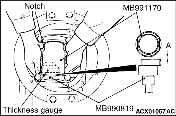
5.Place the following special tools in the side bearing seat of the differential carrier, and position the notch as shown in the illustration. Then install the bearing caps.
- Cylinder gauge (MB991170)
- Drive pinion gauge assembly (MB990819)
6.Use a thickness gauge to measure the clearance (A) between special tools.
7.Remove the bearing caps and special tools.
|
|
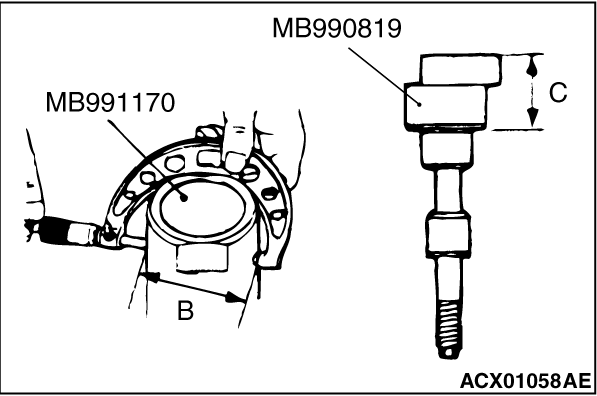
8.Use a micrometer to measure the shown dimensions (B, C) of special tools.
|
|
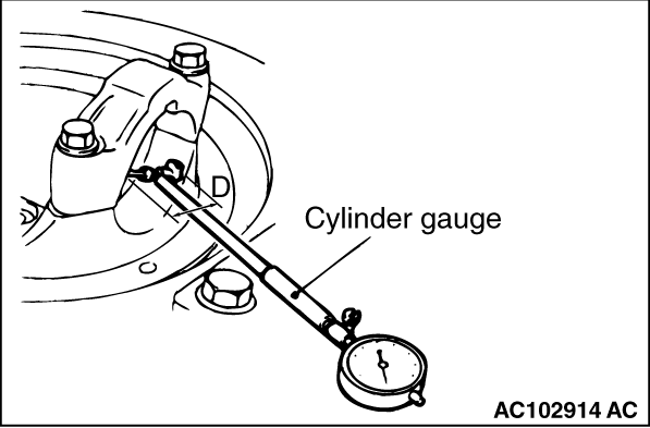
9.Install the bearing cap, and then use a cylinder gauge and micrometer to measure the inside diameter (D) of the bearing cap as shown in the illustration.
10.Calculate the thickness (E) of the required drive pinion front shim by the following formula, and then select a shim which most closely matches this thickness.
E = A + B + C - 1/2D - 100.0 mm
|
|
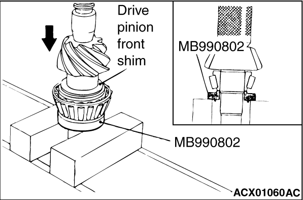
11.Fit the selected drive pinion front shim(s) to the drive pinion, and press-fit the drive pinion front bearing inner race by using special tool bearing installer (MB990802).
|
|
|
Adjust the drive pinion turning torque by using the following procedure:
|
|
|
1.Insert the drive pinion into the gear carrier, and then install the drive pinion spacer, the drive pinion front shim, the drive pinion front bearing inner race, and the companion flange in that order.
| note |
Do not install the oil seal.
|
|

|
2.Tighten the companion flange self-locking nut to the specified torque while holding the companion flange with special tool front hub and flange yoke holder (MB990767).
Tightening torque: 216 ± 29 N·m
|

|
3.
| caution |
There should be no gear oil adhered to the bearing.
|
Use the following special tools to measure the drive pinion turning torque (without the oil seal).
- Preload socket (MB990326)
- Torque wrench (MB990685)
Standard value:
|
|
Bearing division
|
Bearing lubrication
|
Turning torque
|
New
|
None (with anti-rust agent)
|
0.83 - 1.19 N·m
|
|
|

|
4.If the drive pinion turning torque is not within the range of the standard value, adjust the preload by replacing the drive pinion front shim(s) or the drive pinion spacer.
| note |
When selecting the drive pinion front shims, if the number of shims is large, reduce the number of shims to a minimum by selecting the drive pinion spacers.
Select the drive pinion spacer from the following two types.
|
|
|
Height of drive pinion spacer mm
|
Identification colour
|
56.67
|
White
|
57.01
|
-
|
|
|

|
5.Remove the companion flange and drive pinion again. Then, after inserting the drive pinion front bearing inner race into the gear carrier, use special tool oil seal installer (MB990031 or MB990699) to press-fit the oil seal.
|
|
6.Install the drive pinion assembly and companion flange with the mating marks properly aligned. Tighten the companion flange self-locking nut to the specified torque while holding the companion flange with special tool.
Tightening torque: 216 ± 29 N·m
|
|
7.Use special tools to measure the drive pinion turning torque (with drive pinion oil seal) to verify that the drive pinion turning torque complies with the standard value.
Standard value:
|
|
Bearing division
|
Bearing lubrication
|
Turning torque
|
New
|
None (with anti-rust agent)
|
0.93 - 1.28 N·m
|
Gear oil applied
|
0.97 - 1.32 N·m
|
|
8.If the turning torque is not within the standard value, check the tightening torque of the companion flange self-locking nut, and the installation of the oil seal.
|
|
|
Adjust the differential gear backlash by the following procedure:
|
|
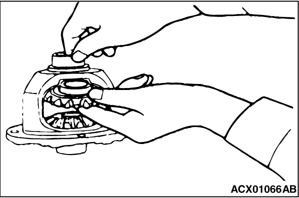
1.Assemble the side gears, side gear spacers, pinion gears and pinion washers into the differential case.
2.Temporarily install the pinion shaft.
| note |
Do not drive in the lock pin yet.
|
|

|
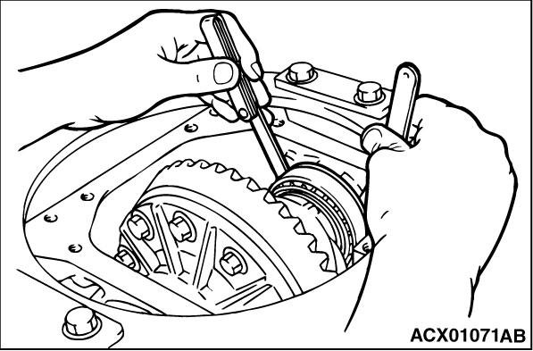
3.Insert a wedge between the side gear and the pinion shaft to lock the side gear.
4.While locking the side gear with the wedge, measure the differential gear backlash with a dial indicator on the pinion gear.
Measure by the same procedure for the other pinion gear.
Standard value: 0.01 - 0.250 mm
5.If the backlash exceeds the standard value, adjust it by replacing the side gear spacers.
6.If adjustment is not possible, replace the side gears and pinion gears as a set.
7.Measure the differential gear backlash once again, and confirm that it is within the standard.
|
|
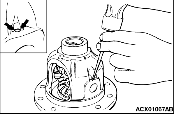
1.Align the pinion shaft lock pin hole with the differential case lock pin hole, and drive in the lock pin.
2.Stake the lock pin with a punch at two points.
|
|
|
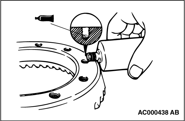
1.Clean the drive gear attaching bolts.
|

|
2.Remove the adhesive adhered to the threaded holes of the drive gear by turning the tap (M10 x 1.25), and then clean the threaded holes by applying compressed air.
|
|
3.Apply the specified sealant to the threaded holes of the drive gear.
Specified sealant: LOCKTITE No.271 or No.270 or equivalent
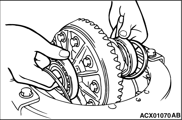
4.Install the drive gear onto the differential case with the mating marks properly aligned. Tighten the bolts to the specified torque in a diagonal sequence.
Tightening torque: 84 ± 4 N·m
|

|
Use special tool bearing installer (MB990802) to press-fit the differential side bearing inner races into the differential case.
|
|
|
Adjust the drive gear backlash by the following procedures:
|
|
1.Install the side bearing spacers, which are thinner than those removed, to the side bearing outer races, and then mount the differential case assembly into the gear carrier.
| note |
Select side bearing spacers with the same thickness for both the drive pinion side and the drive gear side.
|
|
|
2.Push the differential case assembly to one side, and measure the clearance between the gear carrier and the side bearing adjusting spacer with a feeler gauge.
|

|
3.Measure the thickness of the side bearing adjusting spacers on one side, select two pairs of spacers which correspond to that thickness plus one half of the clearance plus 0.05 mm, and then install one pair each to the drive pinion side and the drive gear side.
|
|
4.Install the side bearing adjusting spacers and differential case assembly, as shown in the illustration, to the gear carrier.
|

|
5.Tap the side bearing adjusting spacers with special tool bar (MB990939) to fit them to the side bearing outer race.
|

|
6.Align the mating marks on the gear carrier and the bearing cap, and then tighten the bearing cap.
Tightening torque: 59 ± 4 N·m
|
|
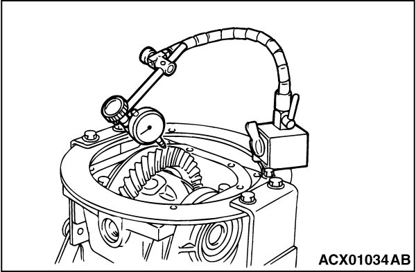
7.With the drive pinion locked in place, measure the drive gear backlash with a dial indicator on the drive gear.
| note |
Measure at four points or more on the circumference of the drive gear.
|
Standard value: 0.11 - 0.16 mm
|
|
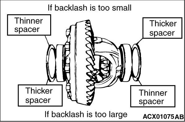
8.Change the side bearing adjusting spacers as illustrated, and then adjust the drive gear backlash between the drive gear and the drive pinion.
| note |
When increasing the number of side bearing adjusting spacers, use the same number for each, and as few as possible.
|
9.Check the drive gear and drive pinion for tooth contact. If poor contact is evident, make adjustment. (Refer to  .) .)
|
|
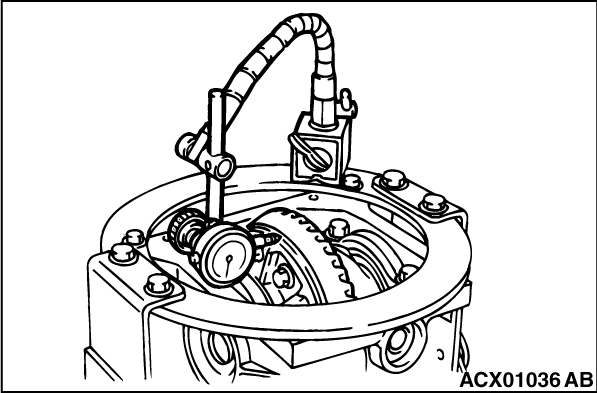
10.Measure the drive gear runout at the shoulder on the reverse side of the drive gear.
Limit: 0.05 mm
11.If the drive gear runout exceeds the limit, reinstall by changing the phase of the drive gear and differential case, and remeasure.
12.If adjustment is not possible, replace the differential case or replace the drive gear and drive pinion as a set.
|
)
)
)
)
)
)
)
)
)
)
)
)
)
)
)
)
)
)
)
)
)
)
)
)
)
)
)
)
)
)