
|
1.Remove one retainer bolt from the backing plate.
|
|
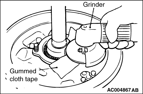
2.Apply gummed cloth tape around the edge of the bearing case for protection.
| caution |
Be careful not to damage the bearing case and the axle shaft.
|
3.As shown in the figure, hold the axle shaft. Using a grinder, shave off a point of its circumference locally until the wall thickness become as follows:
- 1.0 - 1.5 mm for axle shaft side
- 2.0 mm for bearing side
| caution |
Be careful not to damage the bearing case and the axle shaft.
|
|

|
4.Fix the axle shaft and shave off the remaining 2.0 mm on the side of the retainer bearing.
| caution |
Be careful not to damage the axle shaft.
|
|
|
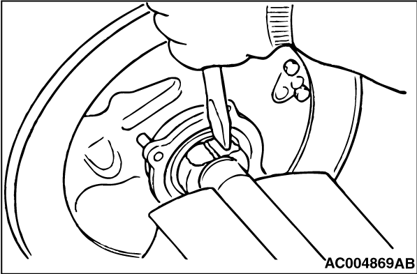
5.Cut in with a chisel the place where the retainer ring has been shaven and remove the retainer ring.
|
|
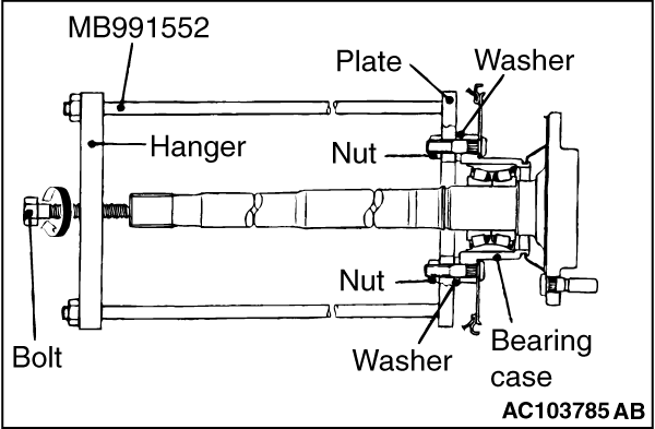
1.Secure special tool axle shaft bearing and case remover (MB991552) to the bearing case bolts with the nuts and adjust the height of the hanger. Then install the washers, plate and nuts in that order.
| note |
The washers are used to eliminate the difference in height of the bearing case so that the plate and the bearing case are parallel.
|
| caution |
The hanger and plate should be placed so that they are parallel.
|
2.Place the end of the bolt against the centre of the axle shaft, and then tighten the bolt to remove the axle shaft from the bearing case assembly.
|
|
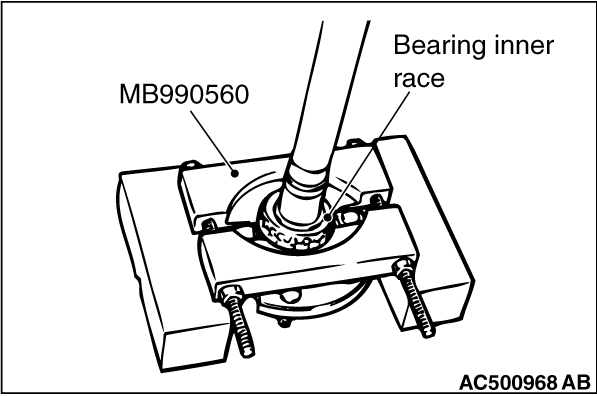
Install special tool rear axle shaft bearing remover (MB990560) as shown in the illustration, and then use a press to remove the outer bearing inner race from the axle shaft.
|
|
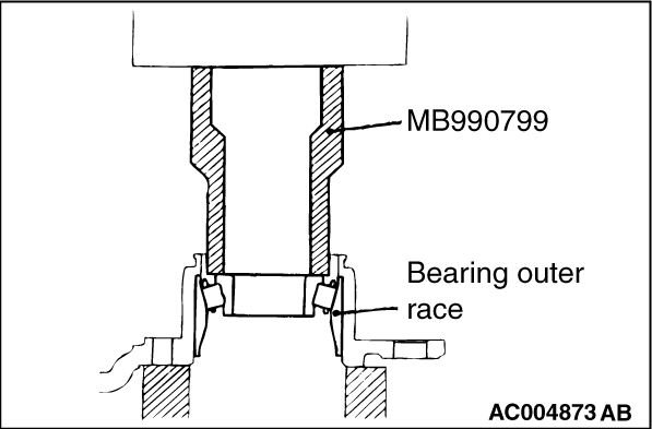
Reinstall the outer bearing inner race that was removed previously. Use special tool ball joint remover and installer A (MB990799) and a press to remove the bearing outer race.
|

|
Use special tool rear suspension bushing base (MB990890 or MB990891) to press-fit the bearing outer race to the bearing case.
|

|
1.Apply multipurpose grease to the outside of the oil seal.
2.Use the following special tools, press-fit the oil seal into the bearing case until it is flush with the face of the bearing case.
- Installer adapter (MB990936)
- Bar (MB990938)
3.Apply multipurpose grease to the lips of the oil seal.
|

|
1.Apply multipurpose grease to the roller surface and ends of the bearing.
2.Pass the axle shaft through the bearing case and the inner bearing inner race and outer bearing inner race.
| caution |
Both the inner bearing inner race and outer bearing inner race should be press-fitted together.
|
3.Use special tool ball joint remover and installer A (MB990799) to press-fit the inner bearing inner race and outer bearing inner race to the axle shaft.
|
|
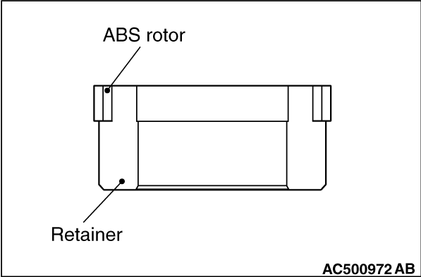
1.Press-fit the ABS rotor to the retainer until it will contact the retainer edge part.
|
|
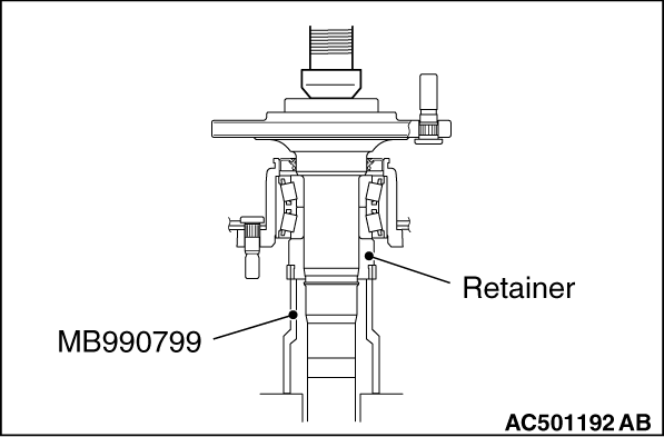
2.Use special tool ball joint remover and installer A (MB990799) to press-fit the retainer with ABS rotor to the axle shaft. Check that the press-fitting force is at the standard value.
3.If the initial press-fitting force is less that the standard value, replace the axle shaft.
Standard value:
|
|
Initial press-fitting force N
|
29,400 or more
|
Final press-fitting force N
|
98,000 - 107,800
|
|
|

|
1.After installing the snap ring, measure clearance (A) between the snap ring and the retainer with a feeler gauge. Check that it is within the standard value.
Standard value (A): 0 - 0.166 mm
2.If the clearance exceeds the standard value, change the snap ring so that the clearance is at the standard value.
|
|
Thickness of snap ring mm
|
Identification colour
|
2.17
|
-
|
2.01
|
Yellow
|
1.85
|
Blue
|
1.69
|
Purple
|
1.53
|
Red
|
|
Example:
Clearance 2.0 mm
Standard value 0 - 0.166 mm
Thickness of snap ring 1.85 mm
|
)

)
)
)
)
)
)
)
)
)
)
)
)
)