REMOVAL AND INSTALLATION


caution
  • *: Indicates parts which should be temporarily tightened, and then fully tightened with the vehicle on the earth in an unladen condition.
  • When the suspension is adjusted or replaced, the calibration of steering wheel sensor must be performed. (Refer to GROUP 35C, On-vehicle Service ). <Vehicles with ASTC>
Post-installation Operation
  • Check the dust cover for cracks or damage by pushing it with your finger.
  • Wheel Alignment Check and Adjustment (Refer to ).


Removal steps


1.
Front wheel speed sensor bracket mounting bolt <Vehicles with ABS>


2.
Brake hose
<<A>>

3.
Upper arm ball joint and knuckle connection
<<B>>

4.
Upper arm assembly and front frame connection


5.
Upper arm assembly

>>A<<
6.
Rebound stopper


7.
Upper arm ball joint assembly

REMOVAL SERVICE POINTS


<<A>> UPPER ARM BALL JOINT AND KNUCKLE DISCONNECTION


caution
  • Do not remove the nut from ball joint. Loosen it and use special tool to avoid possible damage to ball joint threads.
  • Hang special tool with a cord to prevent it from falling.
  • Because it is very dangerous when the ball joint comes off, raise the lower arm using a jack or similar device, making sure that the rebound stopper is free from any reaction force.

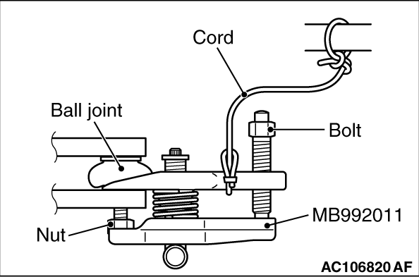
1.Install special tool ball joint remover (MB992011) as shown in the figure.

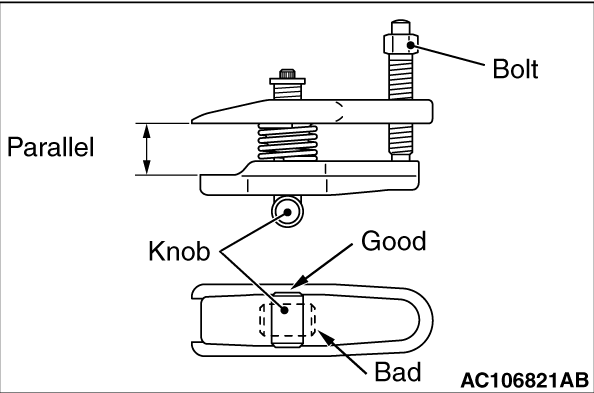
2.Turn the bolt and knob as necessary to make the jaws of special tool parallel, tighten the bolt by hand and confirm that the jaws are still parallel.
note When adjusting the jaws in parallel, make sure the knob is in the position shown in the figure.
3.Tighten the bolt with a wrench to disconnect the ball joint.

<<B>> UPPER ARM ASSEMBLY AND FRONT FRAME CONNECTION REMOVAL


Remove the mounting bolts and nuts from the shock absorber assembly, and secure a working space.

INSTALLATION SERVICE POINT


>>A<< REBOUND STOPPER INSTALLATION


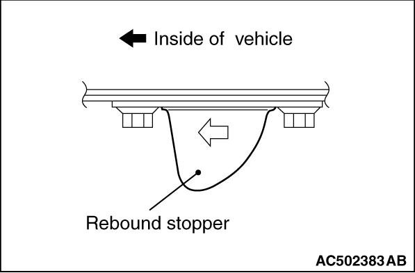
Install the rebound stopper with its arrow mark pointing toward inside the vehicle.