
|
If the front brake disc is seized, install a M8 × 1.25-mm bolts as shown, and remove the disc by tightening the bolts evenly and gradually.
|
|
|
Check the brake drag force as follows.
|

|
1.Using a spring balance, measure the hub sliding torque in the forward direction.
|
|
2.
| caution |
Do not let any oil, grease or other contamination get onto the friction surfaces of the pads and brake discs.
|
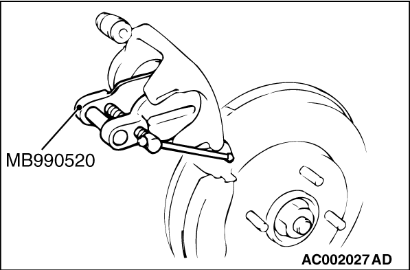
Clean the piston and insert into cylinder with special tool disc brake piston expander (MB990520).
3.Install the pad clip and pad to the calliper support, and tighten the pin bolt to the specified torque.
Tightening torque: 27 ± 4 N·m
4.Start the engine, and depress the brake pedal forcibly two or three times. Then, stop the engine.
5.Turn the brake disc 10 times in the forward direction.
|

|
6.Using a spring balance, measure the hub sliding torque in the forward direction.
7.Obtain the disc brake drag force (difference between measured values of item 1 and item 6).
Standard value: 56 N or less
8.If the brake drag force exceeds the standard value, disassemble the piston to check for fouling and rust on the piston sliding section and deterioration of piston or seal, and check the sliding status of the pin.
|
)

)
)
)
)