|
| caution |
Before connecting or disconnecting the M.U.T.-III, turn the ignition switch to the "LOCK"
(OFF) position.
|
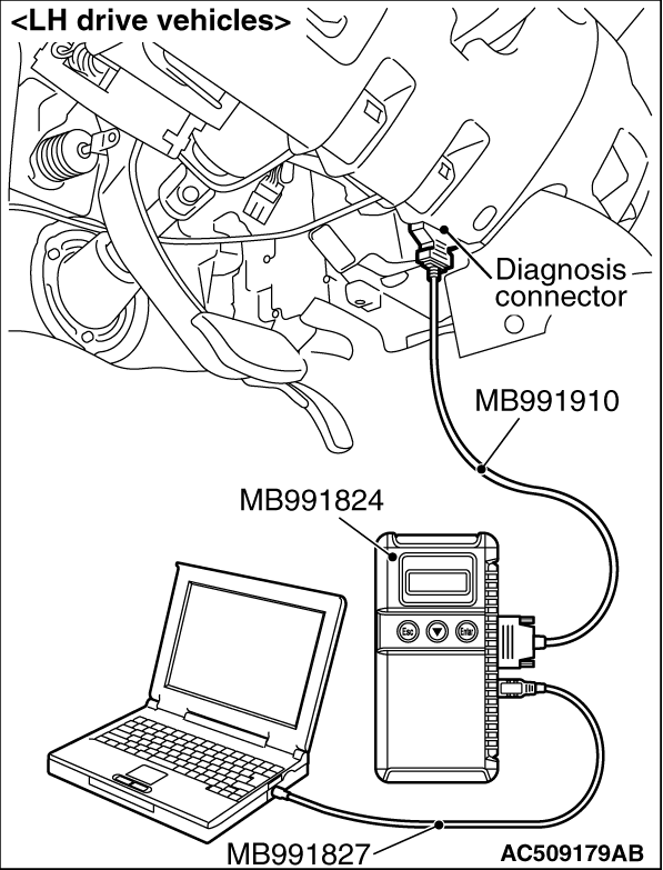
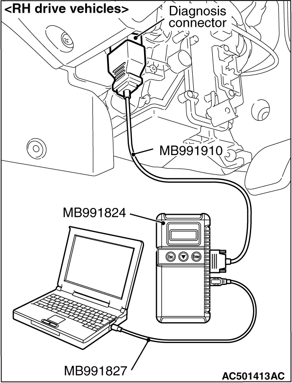
(1)Connect M.U.T.-III to the 16-pin diagnosis connector.
(2)Turn the ignition switch to the "ON" position.
(3)Diagnose the CAN bus line.
(4)Turn the ignition switch to the "LOCK" (OFF) position.
Q.
Is the check result normal?
 Go to Step 3. Go to Step 3.
 Repair the CAN bus line (Refer to GROUP 54C, CAN bus line Diagnostic flow Repair the CAN bus line (Refer to GROUP 54C, CAN bus line Diagnostic flow  ).
Then go to Step 2. ).
Then go to Step 2.
|
|
| caution |
Before connecting or disconnecting the M.U.T.-III, turn the ignition switch to the "LOCK"
(OFF) position.
|
(1)Turn the ignition switch to the "ON" position.
(2)Erase the diagnosis code.
(3)Drive the vehicle at 15 km/h or more for 5 seconds or more.
(4)Turn the ignition switch to the "LOCK" (OFF) position.
(5)Turn the ignition switch to the "ON" position.
(6)Check if the diagnosis code is set.
(7)Turn the ignition switch to the "LOCK" (OFF) position.
Q.
Is code No.C1216 set?
Go to Step 3.
The procedure is complete.
|
|
|
Check whether the rear left wheel speed sensor or its mounting bolts are loosened.
|
|
|
Q.
Is the check result normal?
|
|
|
Reinstall the wheel speed sensor correctly. Then go to Step 11.
|
|
|
|
|
|
Check the rear left wheel speed sensor (Refer to ).
|
|
|
Q.
Is the check result normal?
|
|
|
Replace the rear left wheel speed sensor. Then go to Step 11.
|
|
|
|
|
|
- Check the axle shaft bearing (Refer to GROUP 27, On-vehicle service - Axle
shaft axial play check ).
|
|
|
Q.
Is the check result normal?
|
|
|
NO (wheel bearing axial play is not within the standard value) : Replace the rear axle shaft bearing (Refer to GROUP 27, Axle shaft assembly ).
Then go to Step 11. : Replace the rear axle shaft bearing (Refer to GROUP 27, Axle shaft assembly ).
Then go to Step 11.
|
|
|
|
|
|
Check the rear right ABS rotor, for foreign material or deformation.
|
|
|
Q.
Is the check result normal?
|
|
|
NO (wheel bearing axial play is not within the standard value) : If the ABS rotor is contaminated with foreign material, clean it. If the rear
axle shaft bearing is deformed, replace it (Refer to GROUP 27, Axle shaft assembly ).
Then go to Step 11.
|
|
|
|
|
Q.
Is the check result normal?
Go to Step 10.
Repair or replace the damaged component(s). Then go to Step 11.
|
|
|
Check the rear left wheel speed sensor. For the applicable inspection procedure, refer
to .
|
|
|
Q.
Is the check result normal?
|
|
Q.
Is the check result normal?
Go to Step 11.
Repair the wiring harness. Then go to Step 12.
|
|
Check again if the diagnosis code is set.
(1)Turn the ignition switch to the "ON" position.
(2)Erase the diagnosis code.
(3)Drive the vehicle at 15 km/h or more for 5 seconds or more.
(4)Turn the ignition switch to the "LOCK" (OFF) position.
(5)Turn the ignition switch to the "ON" position.
(6)Check if the diagnosis code is reset.
(7)Turn the ignition switch to the "LOCK" (OFF) position.
Q.
Is code No.C1216set?
Replace the hydraulic unit assembly (integrated with ASTC-ECU). Then go to Step
11.
It can be assumed that this malfunction is intermittent. Refer to GROUP 00, How
to Use Troubleshooting/Inspection Service Points - How to Cope with Intermittent
Malfunction .
|
|
|
Check that the ABS warning lamp, ASTC indicator lamp and ASTC OFF indicator lamp goes
out when the vehicle is driven at 15 km/h for 5 seconds or more.
|
|
|
Q.
Does the ABS warning lamp, ASTC indicator lamp and ASTC OFF indicator lamp goes out?
|
|
|
It can be assumed that this malfunction is intermittent. Refer to GROUP 00, How
to Use Troubleshooting/Inspection Service Points - How to Cope with Intermittent
Malfunction .
|
|
|
|
|
(1)Turn the ignition switch to the "ON" position.
(2)Erase the diagnosis code.
(3)Drive the vehicle at 15 km/h or more for 5 seconds or more.
(4)Turn the ignition switch to the "LOCK" (OFF) position.
(5)Turn the ignition switch to the "ON" position.
(6)Check if the diagnosis code is set.
(7)Turn the ignition switch to the "LOCK" (OFF) position.
Q.
Is code No.C1216 set?
It can be assumed that this malfunction is intermittent. Refer to GROUP 00, How
to Use Troubleshooting/Inspection Service Points - How to Cope with Intermittent
Malfunction .
The procedure is complete.
|
)
)
)
)
)
)
)
)