|
| caution |
Before connecting or disconnecting the M.U.T.-III, turn the ignition switch to the "LOCK" (OFF) position.
|
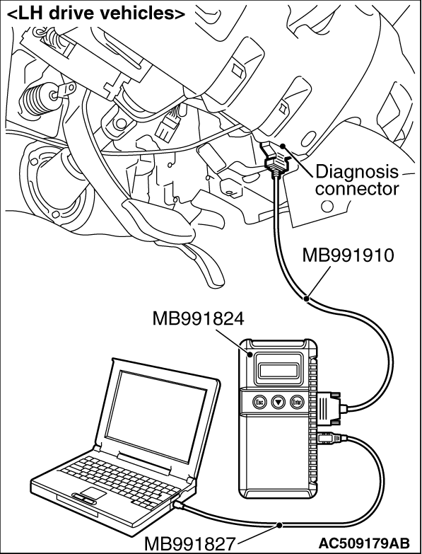
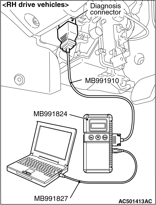
(1)Connect M.U.T.-III to the 16-pin diagnosis connector.
(2)Turn the ignition switch to the "ON" position.
(3)Diagnose the CAN bus line.
(4)Turn the ignition switch to the "LOCK" (OFF) position.
Q.
Is the check result normal?
 Go to Step 3. Go to Step 3.
 Repair the CAN bus line (Refer to GROUP 54C, CAN bus line Diagnostic flow Repair the CAN bus line (Refer to GROUP 54C, CAN bus line Diagnostic flow  ). Then go to Step 2. ). Then go to Step 2.
|
|
| caution |
Before connecting or disconnecting the M.U.T.-III, turn the ignition switch to the "LOCK" (OFF) position.
|
(1)Turn the ignition switch to the "ON" position.
(2)Erase the diagnosis code.
(3)Turn the ignition switch to the "LOCK" (OFF) position.
(4)Turn the ignition switch to the "ON" position.
(5)Check if the diagnosis code is set.
(6)Turn the ignition switch to the "LOCK" (OFF) position.
Q.
Is code No.C1291 set?
Go to Step 3.
The procedure is complete.
|
|
|
Q.
Is the check result normal?
|
|
|
NO <M/T> : Check the back-lamp switch. (Refer to GROUP 22B, Transmission inspection .) Then go to Step 5. : Check the back-lamp switch. (Refer to GROUP 22B, Transmission inspection .) Then go to Step 5.
|
|
|
|
|
|
NO <A/T> : Check if the automatic transmission outputs a diagnosis code. (Refer to GROUP 23A, Troubleshooting .) Then go to Step 5.
|
|
|
|
|
|
Q.
Is the check result normal?
|
|
|
Repair the wiring harness. Then go to Step 6.
|
|
|
|
|
Check again if the diagnosis code is set.
(1)Turn the ignition switch to the "ON" position.
(2)Erase the diagnosis code.
(3)Turn the ignition switch to the "LOCK" (OFF) position.
(4)Turn the ignition switch to the "ON" position.
(5)Check if the diagnosis code is set.
(6)Turn the ignition switch to the "LOCK" (OFF) position.
Q.
Is code No.C1291 set?
Replace the hydraulic unit assembly (integrated with ASTC-ECU). Then go to Step 6.
It can be assumed that this malfunction is intermittent. Refer to GROUP 00, How to Use Troubleshooting/Inspection Service Points - How to Cope with Intermittent Malfunction .
|
|
Check again if the diagnosis code is set.
(1)Turn the ignition switch to the "ON" position.
(2)Erase the diagnosis code.
(3)Turn the ignition switch to the "LOCK" (OFF) position.
(4)Turn the ignition switch to the "ON" position.
(5)Check if the diagnosis code is set.
(6)Turn the ignition switch to the "LOCK" (OFF) position.
Q.
Is code No.C1291 set?
Go to Step 1.
The procedure is complete.
|
)
)