|
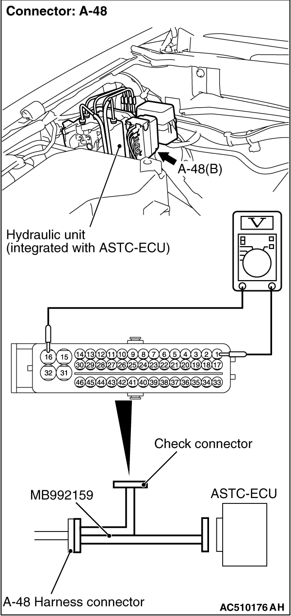
1.Disconnect the ASTC-ECU connector A-48, and then use special tool ASC Check Harness (MB992159)
to measure the voltages between terminals (16) and each terminal other than terminal (31) as
well as between terminal (31) and each terminal other than terminal (16.)
2.The terminal layouts are shown in the illustrations below.
| note |
Do not measure terminal voltage for approximately three seconds after the ignition switch
is turned "ON." The ASTC-ECU performs the initial check during that period.
|
Terminal No.
|
Check item
|
Checking requirements
|
Normal condition
|
1
|
G and yaw rate sensor power supply
|
Always
|
System voltage
|
7
|
Stop lamp switch input
|
Ignition switch: "ON"
|
Stop lamp switch: "ON"
|
System voltage
|
Stop lamp switch: "OFF"
|
Approximately 0 V
|
15
|
Motor power supply
|
Always
|
System voltage
|
32
|
Solenoid valve power supply
|
Always
|
System voltage
|
33
|
ASTC-ECU power supply
|
Ignition switch: "ON"
|
System voltage
|
Ignition switch: "START"
|
Approximately 0 V
|
36
|
ASC switch output
|
Ignition switch: "ON"
|
System voltage
|
|

|
1.Disconnect the connector A-48, and connect special tool ASC Check Harness (MB992159) to
the wiring harness-side connector.
| note |
Do not connect special tool ASC Check Harness (MB992159) to the ASTC-ECU.
|
2.Measure the resistance and continuity between the terminals indicated in the table
below.
Terminal No.
|
Signal
|
Normal condition
|
16 -
body earth
|
Earth
|
Less than 2 ohms
|
31 -
body earth
|
Earth
|
Less than 2 ohms
|
|
)
)