REMOVAL AND INSTALLATION


warning For vehicles with SRS, before removing the steering gear, refer to GROUP 52B, Service Precautions () and Air Bag Module(s) and Clock Spring (). Centre the front wheels. Failure to do so may damage the SRS clock spring and render the SRS system inoperative, risking serious injury.
Pre-removal Operation
  • Power Steering Fluid Draining (Refer to ).
  • Front Differential and Propeller Shaft disconnection (Refer to GROUP 25, Propeller Shaft ).
  • Wheel Speed Sensor Harness Bracket, Free Wheel Actuator Connector and Hose disconnection (Refer to GROUP 26, Differential Carrier and Free Wheeling Clutch ).
  • Differential Mount Bracket Front Mounting Bolts removal (Refer to GROUP 26, Front Differential Mount ).

Post-installation Operation
  • Differential Mount Bracket Front Mounting Bolts installation (Refer to GROUP 26, Front Differential Mount ).
  • Wheel Speed Sensor Harness Bracket, Free Wheel Actuator Connector and Hose connection (Refer to GROUP 26, Differential Carrier and Free Wheeling Clutch ).
  • Front Differential and Propeller Shaft Connection (Refer to GROUP 25, Propeller Shaft ).
  • Fill Power Steering Fluid and bleed air (Refer to ).
  • Check the Dust Cover for Chacks or Damage by Pushing it with Finger.
  • Check the Steering Angle (Refer to ).


Removal steps


1.
Split pin
<<A>>

2.
Tie rod end and knuckle connection

>>B<<
3.
Tie rod end


4.
Shaft assembly

>>A<<
5.
Return tube connection


6.
O-ring

>>A<<
7.
Pressure tube connection


8.
O-ring


9.
Clamp
<<B>>

10.
Power steering gear box assembly

REMOVAL SERVICE POINTS


<<A>> TIE ROD END AND KNUCKLE DISCONNECTION


caution
  • Do not remove the nut from ball joint. Loosen it and use the special tool to avoid possible damage to ball joint threads.

  • Hang the special tool with a cord to prevent it from falling.

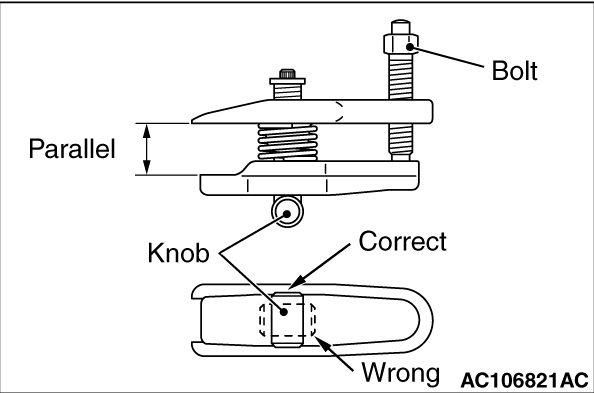
1.Install the special tool ball joint remover (MB991897 or MB992011) as shown in the figure.

2.Turn the bolt and knob as necessary to make the jaws of the special tool parallel, tighten the bolt by hand and confirm that the jaws are still parallel.
note When adjusting the jaws in parallel, make sure the knob is in the position shown in the figure.
3.Tighten the bolt with a wrench to disconnect the tie rod end.
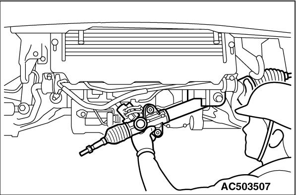
<<B>> POWER STEERING GEAR BOX ASSEMBLY REMOVAL


caution Be sure not to damage the bellows and the tie rod end dust cover when removing the gear box assembly.

INSTALLATION SERVICE POINTS


>>A<< PRESSURE TUBE/RETURN TUBE CONNECTION


Align the paint marks of the steering gear box, pressure tube and return tube.

>>B<< TIE ROD END/LOCK NUT INSTALLATION


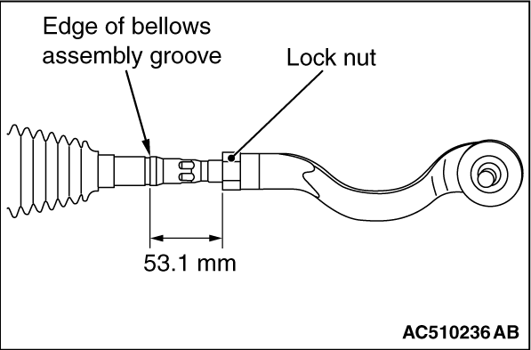
Screw in the tie rod end to achieve the right and left length as illustrated. Lock with the lock nut.
note The lock nuts must be tightened securely only after the steering gear is installed to the vehicle and toe-in is adjusted.