|
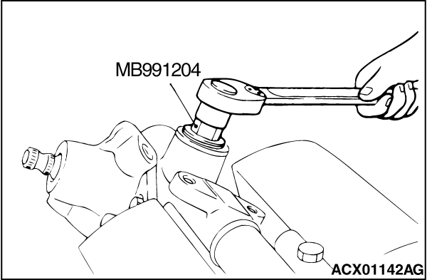
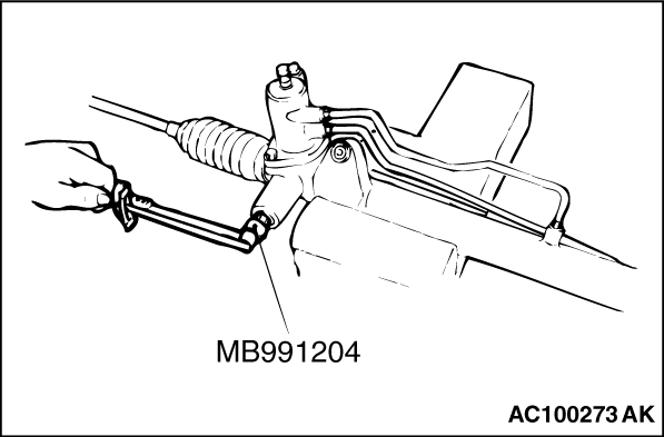
Using special tool torque wrench socket (MB991204) remove the rack support cover from
the steering gear.
|
|
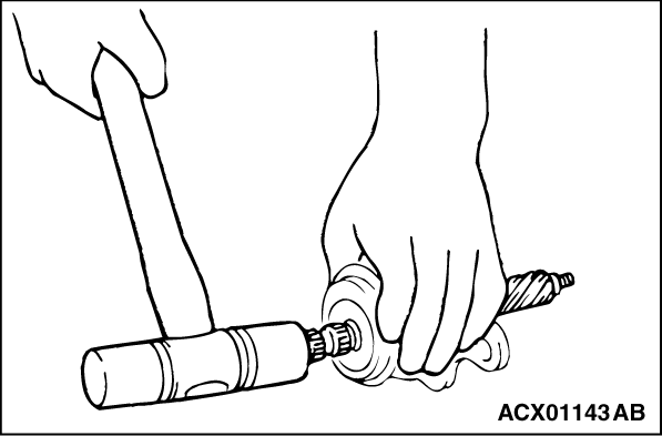
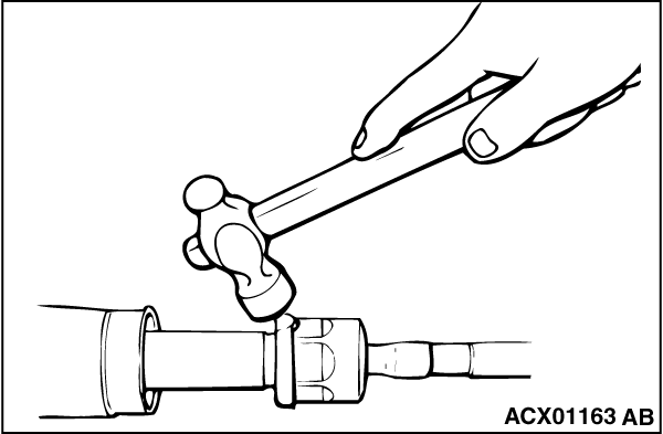
Using a plastic hammer, gently tap the pinion to remove it.
|
|
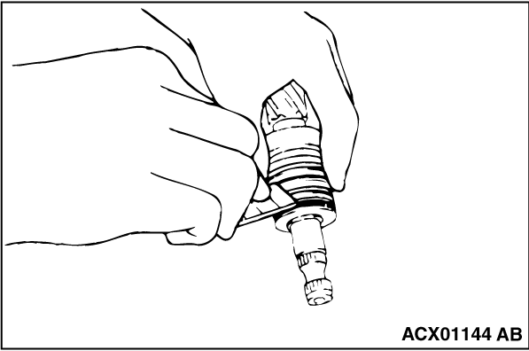
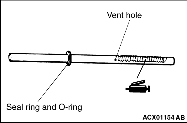
Cut the seal ring and remove it from the pinion and valve assembly or the rack.
|
|
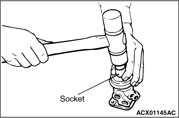
Using a socket, remove the oil seal and the ball bearing from the valve housing simultaneously.
|
|
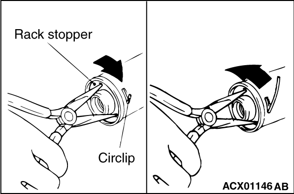
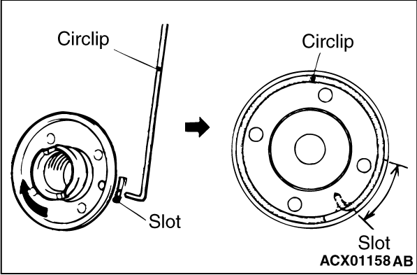
1.Turn the rack stopper clockwise until the end of the circlip comes out of the slot in
the rack housing.
2.Turn the rack stopper anticlockwise to remove the circlip.
|
|
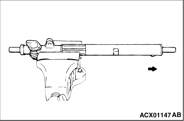
1.Pull out the rack slowly. Take out the rack stopper and the rack bushing at the same time.
|
|
2.
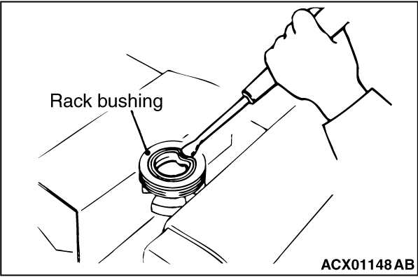
| caution |
Do not damage the oil seal press fitting surface.
|
Partially bend the oil seal and remove it from the rack bushing.
|
|
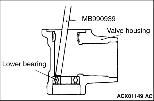
Use a brass bar or special tool brass bar (MB990939) to remove the ball bearing from the
gear housing.
|
|
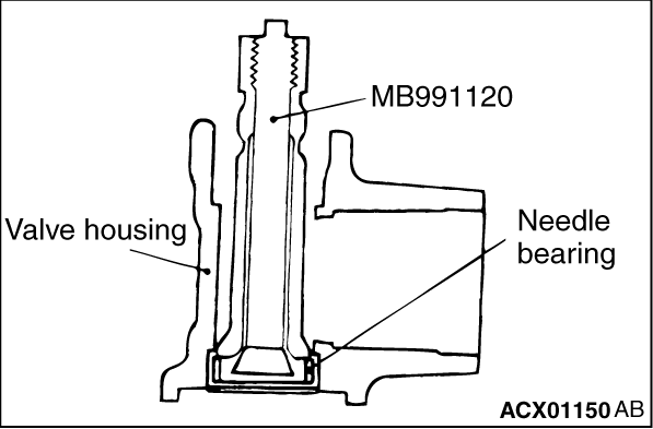
Use special tool needle bearing puller (MB991120) to remove the needle bearing from the
rack housing.
|
|
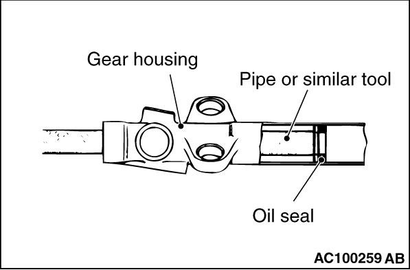
Use a piece of pipe or similar tool to remove the oil seal from the gear housing.
|
|
|
1.Apply a coating of ATF DEXRON III or DEXRON II to the both sides of the oil seal.
|
|
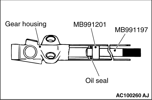
2.Using following special tools, press the oil seal into the rack housing.
- Bar (long type) (MB991197)
- Oil seal and bearing installer (MB991201)
|
|
|
1.Apply ATF DEXRON III or DEXRON II to housing, bearing and oil seal press fitting surface.
|
|
2.
| caution |
Press-fit straight. The valve housing is aluminium, and may become deformed
if press-fit on an angle.
|
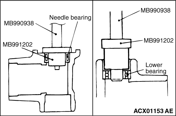
Press fit needle bearing with following special tools.
- Bar (snap-in type) (MB990938)
- Oil seal and bearing installer (MB991202)
|
|
1.
| caution |
Do not close the vent hole in the rack with grease.
|
Apply a coating of repair kit grease to the rack teeth face.
|
|
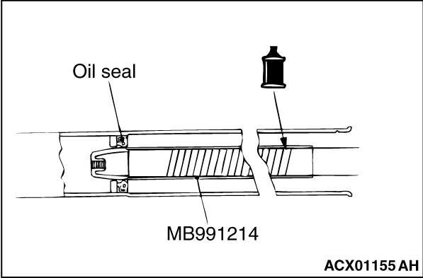
2.Cover rack serrations with special tool oil seal protector (MB991214).
3.Apply ATF DEXRON III or DEXRON II to special oil seal protector (MB991214), and to
the outer surface of the seal ring and the O-ring.
4.Align the centre of the oil seal with the rack to prevent the retainer spring from
slipping. Slowly insert the rack from power cylinder side.
|
|
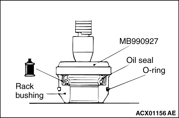
1.Apply ATF DEXRON III or DEXRON II to the outer surface of the oil seal. Using the special
tool installer adapter (MB990927), press in the oil seal until it is flush with the bushing
end face.
|
|
2.Apply ATF DEXRON III or DEXRON II to the oil seal inner surface and the O-ring.
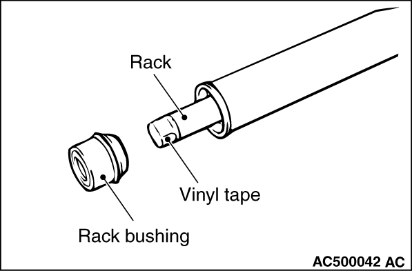
3.Wrap the rack end with plastic tape, and push the rack bushing onto the rack.
|
|
Insert the circlip to the rack stopper hole through cylinder hole. Turn the rack stopper
clockwise and insert the circlip firmly.
|
|
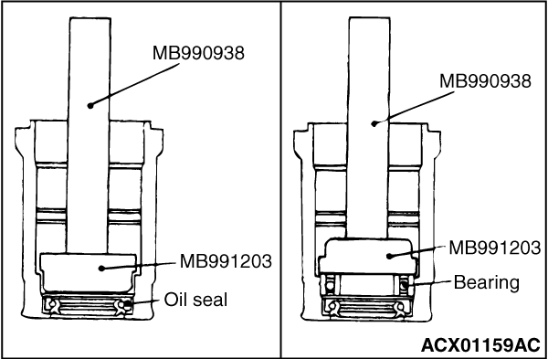
Apply a coating of ATF DEXRON III or DEXRON II to the outside of the upper oil seal/upper
bearing. Using following special tools, press the upper oil seal/upper bearing into
the valve housing.
- MB990938: Bar (Snap-in type)
- MB991203: Oil Seal and Bearing Installer
|
|
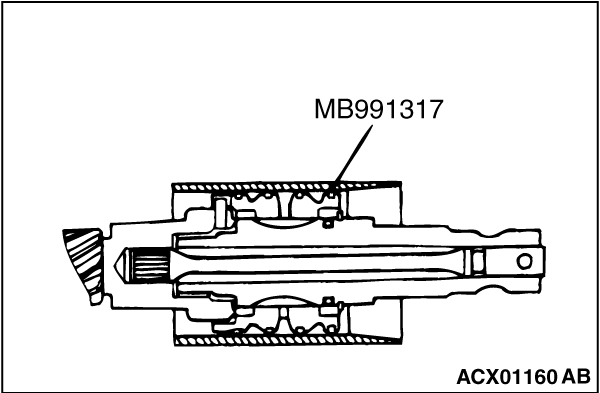
Because the seal rings expand after installation, tighten after installing by using special
tool seal ring installer (MB991317) to compress the rings, or press down by hand.
|
|
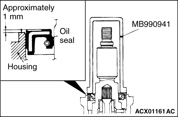
Using special tool torque tube bearing installer (MB990941), press the oil seal into the
valve housing.
|
|
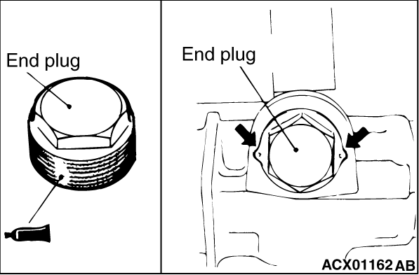
1.Apply specified sealant to the threaded part of the end plug.
Specified sealant:
3M ATD Part No. 8663 or equivalent
2.Secure the threaded portion of the end plug at two places by using a punch.
|
|
|
1.Position the rack at its centre.
|
|
|
2.Apply specified sealant to the threaded part of the rack support cover.
Specified sealant:
3M ATD Part No. 8663 or equivalent
|
|
3.Use special tool torque wrench socket (MB991204) to tighten the rack support cover.
4.Use the special tools to hold the rack support cover, and then tighten the lock nut
to 59 ± 10 N·m.
|
|
1.
| caution |
- Be sure there is no ratcheting or catching when operating
the rack towards the shaft.
- Measure the total pinion torque through the whole stroke of the rack.
|
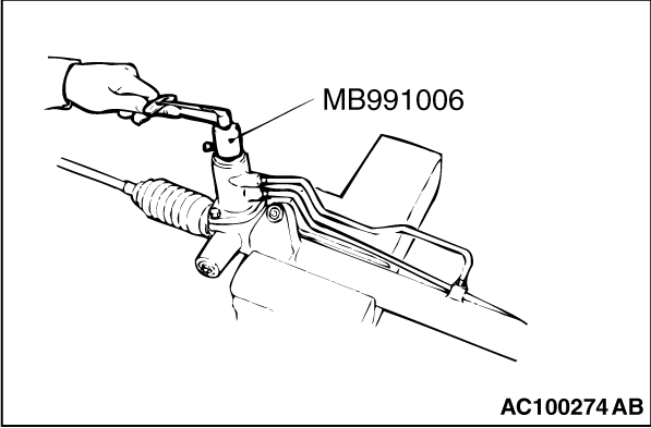
Using special tool preload socket (MB991006), rotate the pinion shaft at the rate of one
rotation in four to six seconds to check the total pinion torque and the change in torque.
Standard value:
Total pinion torque: 0.6 - 1.7 N·m
[Change in torque:
0.4 N·m or less]
2.
| caution |
When adjusting, set at the highest value of the standard value range.
|
| note |
If the total pinion toque cannot be adjusted to the standard value within the specified
return angle, check the rack support cover components and replace any parts if necessary.
|
If the total pinion torque or the change in torque is outside the standard value, move
the rack support cover 0 - 30°, and adjust the pinion torque again.
|
|
After installing the tie rod to the rack, fold tab washer end (two locations) to tie rod
notch.
|
|
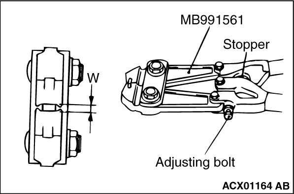
1.Turn the adjusting bolt of special tool boot band crimping tool (MB991561) to adjust the
opening dimension (W) to the standard value.
| note |
The dimension (W) is adjusted by approximately 0.7 mm per one turn.
|
| note |
Do not turn the adjusting bolt more than one turn.
|
Standard value (W): 2.9 mm
<When more than 2.9 mm>: Screw in the adjusting bolt.
<When less than 2.9 mm>: Loosen the adjusting bolt.
|
|
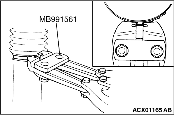
2.
| caution |
- Hold the rack housing, and use special tool boot band crimping
tool (MB991561) to crimp the bellows band securely.
- Crimp the bellows band until special tool boot band crimping tool (MB991561) touches
the stopper.
|
Use special tool boot band crimping tool (MB991561) to crimp the bellows band.
|
|
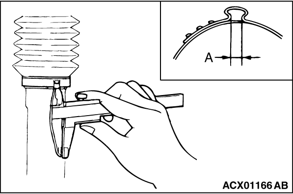
3.Check that crimped width (A) is within the standard value.
Standard value (A): 2.4 - 2.8 mm
<When more than 2.8 mm>: Readjust the dimension (W) of step (1) to the
value calculated by the following equation, and repeat step (2).
W = 5.5 mm - A [Example: if (A) is 2.9 mm, (W) is 2.6 mm.]
<When less than 2.4 mm>: Remove the bellows band, readjust the dimension
(W) of step (1) to the value calculated by the following equation, and use a new bellows band
to repeat steps (2) to (3).
W = 5.5 mm - A [Example: if (A) is 2.3 mm, (W) is 3.2 mm.]
|
|
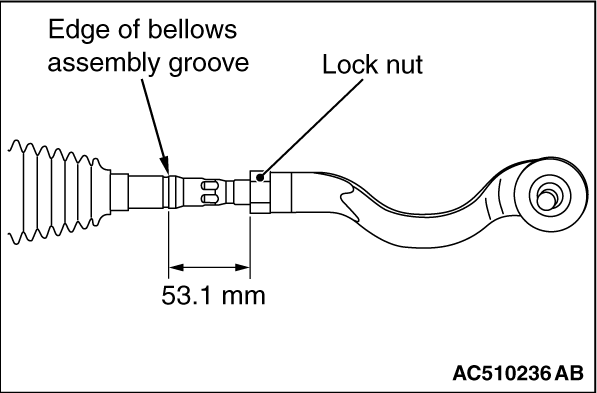
Screw in the tie rod end to achieve the right and left length as illustrated. Lock with
the lock nut.
| note |
The lock nuts must be tightened securely only after the steering gear is installed to
the vehicle and toe-in is adjusted.
|
|
|
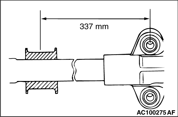
Install the gear mounting rubber to the rack housing so that the distance is as shown
in the illustration.
|
)
)

)
)
)
)
)
)
)
)
)
)
)
)
)
)
)
)
)
)
)
)
)
)
)
)
)
)
)
)
)
)