|
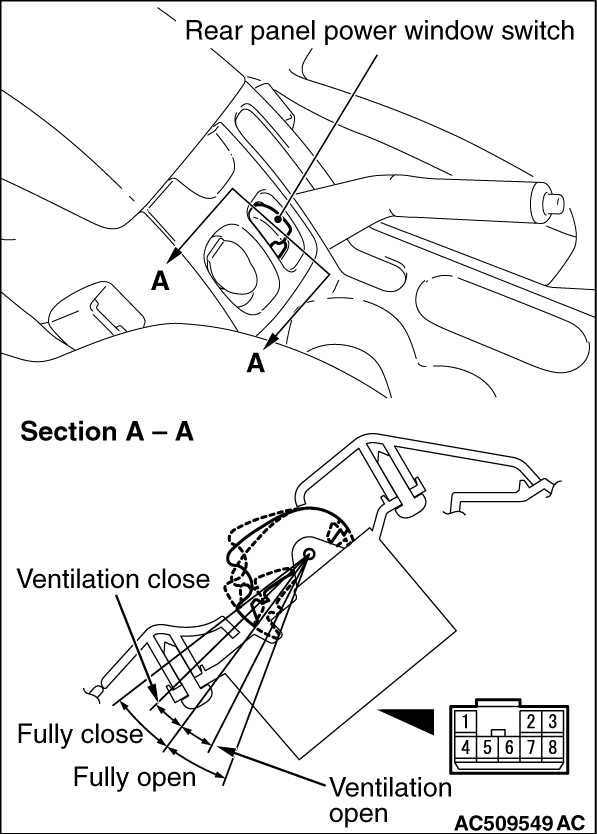
Remove the rear panel power window switch (Refer to GROUP 52A, Rear Floor Console Assembly  ). ).
|
Terminal No.
|
Check item
|
Check condition
|
Normal condition
|
1
|
Output to rear panel power window motor
|
-
|
-
|
2
|
Output to rear panel power window motor
|
-
|
-
|
3
|
-
|
-
|
-
|
4
|
Output to rear panel power window switch
|
Rear panel power window switch (Ventilation open): ON
|
12 V
|
5
|
Output to rear panel power window switch
|
Rear panel power window switch (Fully open/Fully close): ON
|
12 V
|
6
|
Output to rear panel power window switch
|
Rear panel power window switch (Ventilation close): ON
|
12 V
|
7
|
Input from rear panel power window motor (pulse sensor signal)
|
When the rear panel power window are operating
|
0 to 5 V (pulse signal)
|
8
|
Input from rear panel power window motor (power supply to pulse sensor)
|
When the rear panel power window are operating
|
5 V
|
9
|
Power supply from ignition switch (IG1)
|
Ignition switch: ON
|
Battery voltage
|
10
|
Earth
|
Always
|
0 V
|
11
|
Input from rear panel power window motor (pulse sensor earth)
|
-
|
0 V
|
12
|
-
|
-
|
-
|
13
|
-
|
-
|
-
|
14
|
LIN communication line
|
Always
|
0 to 12 V (pulse signal)
|
15
|
-
|
-
|
-
|
16
|
Input from rear panel power window motor (pulse sensor signal)
|
When the rear panel power window are operating
|
0 to 5 V (pulse signal)
|
17
|
-
|
-
|
-
|
18
|
Battery power supply
|
Always
|
Battery voltage
|
)
)