|
|
Whether or not the air bags have deployed, check and service the vehicle after collision as follows:
|


|
1.
| caution |
Refer to that the ignition switch is "LOCK" (OFF) when connecting or disconnecting M.U.T.-III.
|
Connect the M.U.T.-III to the diagnosis connector (Refer to GROUP 00, Diagnosis Function ). ).
2.Read (and write down) all displayed diagnosis codes (Refer to ).
| note |
If battery power supply has been shut down by the collision, the M.U.T.-III cannot communicate with the SRS-ECU. Check and, repair if necessary, the instrument panel wiring harness before the next job.
|
3.Use the M.U.T.-III to read the data list (how long trouble(s) have continued and how often memory have been erased).
Data list
No
|
Data List Item
|
Applicability
|
01
|
Failure continuation time 1
|
Maximum time to be stored: 9,999 minutes (approximately 7 days)
|
02
|
Failure continuation time 2
|
03
|
Elimination times
|
Maximum time to be stored: 250 times
|
4.Erase the diagnosis codes and after waiting 5 seconds or more read (and write down) all displayed diagnosis codes.
|
|
|
1.Replace the following parts with new ones.
- Front impact sensor (Refer to ).
- SRS-ECU (Refer to ).
- Driver’s air bag modules (Refer to ).
- Passenger’s (front) air bag modules (Refer to ).
- Seat belt with pre-tensioner (Refer to ).
|
|
|
2.Check the following parts and replace if there are any malfunctions.
- Clock spring (Refer to ).
- Steering wheel, steering column and shaft assembly
(1)
Check the wiring harness (built into the steering wheel) and connectors for damage, and terminals for deformation.
(2)
Install the air bag module to check fit or alignment with the steering wheel.
(3)
Check the steering wheel for noise, binds or difficult operation and excessive free play.
(4)
Check the steering column shaft shock absorbing mechanism (Refer to GROUP 37, On-vehicle Service ).
- Instrument panel (Refer to GROUP 52A, Instrument panel assembly ).
|
|
|
3.Check the harness for binding, connectors for damage, poor connections, and terminals for deformation (Refer to ).
|
|
|
Check the SRS components. If visible damage such as dents, cracks, or deformation are found on the SRS components, replace them with new ones. Concerning parts removed for inspection, replacement with new parts and cautions in working, refer to
|
|
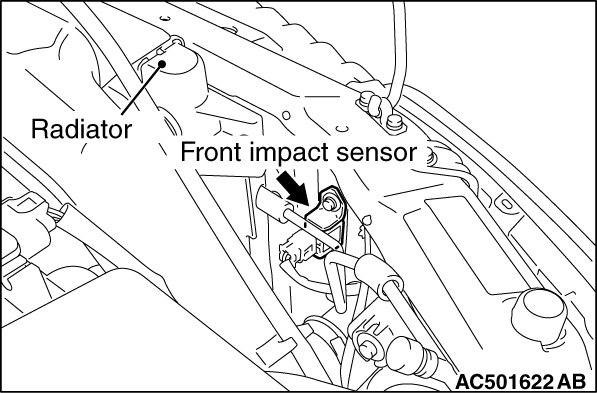
1.Check the head lamp support panel for distortion and rust.
2.Check the front impact sensor for dents, cracks, deformation or rust.
3.Check the front impact sensor wiring harness for binding, check the connector for damage, and check the terminals for deformation.
| note |
The figures show front impact sensors (RH). The front impact sensors (LH) is symmetrical with the front impact sensors (RH).
|
|

|
1.Check the SRS-ECU case for dents, cracks or deformation.
2.Check the connector for damage, and the terminals for deformation.
3.Check the SRS-ECU for installation condition.
|
|
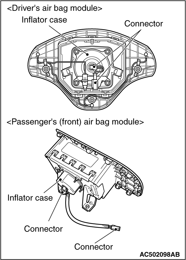
1.Check the pad cover for dents, cracks or deformation.
2.Check the connector for damage, terminals deformities, and the harness for binding.
3.Check the air bag inflator case for dents, cracks or deformities.
4.Check the air bag modules for proper installation.
|

|
1.Check the clock spring connectors and protective tube for damage, and the terminals for deformation.
2.Visually check the case for damage.
|
|
|
1.Check the seat belt for damage or deformation.
|
|
|
2.Check the seat belt with pre-tensioner for cracks or deformation.
|
|
|
3.Check that the unit is installed correctly to the vehicle body.
|
|
|
1.Check the wiring harness (built into the steering wheel) and the connectors for damage, and the terminals for deformation.
|
|
|
2.Install the air bag module to check fit or alignment with the steering wheel.
|
|
|
3.Check the steering wheel for noise, binding or difficult operation and excessive free play.
|
|
|
4.Check the steering column shaft shock absorbing mechanism (Refer to GROUP 37, On-vehicle Service ).
|
|
|
Check harnesses for binding, connectors for damage and terminals for deformation (Refer to ).
|
)
)
)
)
)
)