|
|
Q.
Can the M.U.T.-III communicate with the other systems?
|
|
|
 Refer to GROUP 13A, Troubleshooting Refer to GROUP 13A, Troubleshooting  . .
|
|
|
|
|
|
(1)Disconnect the negative battery terminal.
|

|
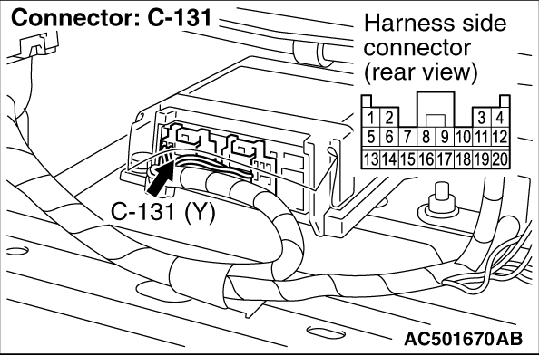
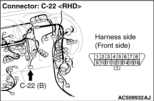
(2)Disconnect SRS-ECU connector C-131 and diagnosis connector C-22, and measure at the wiring harness side.
|

|
(3)
| caution |
Do not insert a test probe into the terminal from of the SRS-ECU connector C-131 its front side directly as the connector contact pressure may be weakened.
|
Resistance measurement between the following terminals.
- SRS-ECU connector C-131 (terminal No.20) and diagnosis connector C-22 (terminal No.7)
OK: Continuity (Less than 2 Ω)
Q.
Is the check results normal?
 Go to Step 3. Go to Step 3.
Go to Step 5.
|
|
|
(1)Disconnect the negative battery terminal.
|
|
(2)Disconnect SRS-ECU connector C-131 and measure at the wiring harness side.
|

|
(3)
| caution |
Do not insert a test probe into the terminal from its front side directly as the connector contact pressure may be weakened.
|
Check for continuity between terminal 18 and body earth.
OK: Continuity (Less than 2 Ω)
Q.
Is the check result normal?
Go to Step 4.
Check the harness wire for open circuit between SRS-ECU connector C-131 (terminal No.18) and earth, and repair if necessary.
|
|
|
(1)Disconnect the negative battery terminal.
|
|
(2)Disconnect SRS-ECU connector C-131 and measure at the wiring harness side.
(3)Connect the negative battery terminal.
(4)Turn the ignition switch to the "ON" position.
|

|
(5)
| caution |
Do not insert a test probe into the terminal from its front side directly as the connector contact pressure may be weakened.
|
Voltage measurement between terminals 13, 16 and body earth.
OK: 9 V or more
Q.
Is the check result normal?
Go to Step 7.
Go to Step 6.
|
|
Q.
Is the check result normal?
An intermittent malfunction is suspected (Refer to GROUP 00, How to Cope with Intermittent Malfunction ).
Check the harness wires for open or short circuit between SRS-ECU connector C-131 (terminal No.20) and diagnosis connector C-22 (terminal No.7) and repair if necessary.
|
|
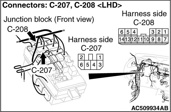
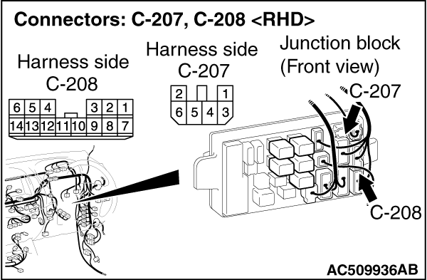
| note |
Prior to the wiring harness inspection, check junction block connectors C-207 and C-208, and repair if necessary.
|
Q.
Is the check result normal?
An intermittent malfunction is suspected (Refer to GROUP 00, How to Cope with Intermittent Malfunction ).
Check the harness wires for open or short circuit between SRS-ECU connector C-131 (terminal No.13, 16) and ignition switch connector C-307, and repair if necessary.
|
|
|
Q.
Does the M.U.T.-III communicate normally with the SRS system?
|
|
|
An intermittent malfunction is suspected (Refer to GROUP 00, How to Cope with Intermittent Malfunction ).
|
|
|
|
|
|
Replace the SRS-ECU (Refer to ).
|
|
|
|
)
)
)
)
)
)
)
)
)
)