REMOVAL AND INSTALLATION


warning
  • Disconnect the negative battery terminal and wait for 60 seconds or more before starting work. Furthermore, the disconnected battery terminal should be covered with tape to insulate it.
  • Never attempt to disassemble or repair the air bag modules or clock spring. If faulty, replace it.
  • Do not drop the air bag modules or clock spring or allow contact with water, grease or oil. Replace it if a dent, crack, deformation or rust is detected.
  • The removed air bag module should be stored in a clean, dry place with the deployment surface facing up. Do not place anything on top of it.
  • Do not expose the air bag modules to temperatures over 93°C.
  • After deployment of an air bag, replace the clock spring with a new one.
  • Wear gloves and safety glasses when handling air bags that have already deployed.
  • An undeployed air bag module should only be disposed of in accordance with the procedures (Refer to ).

<DRIVER’S AIR BAG MODULE AND CLOCK SPRING>


Pre-removal Operation
  • Disconnect the Negative Battery Terminal.


Air bag module removal steps
<<A>>

1.
Cover


·
Horn connector connection
<<B>>

·
Driver’s air bag module connector connection
<<C>>

2.
Driver’s air bag module
<<D>>

3.
Steering wheel


Clock spring removal steps
<<A>>

1.
Cover


·
Horn connector connection
<<B>>

·
Driver’s air bag module connector connection
<<C>>

2.
Driver’s air bag module
<<D>>

3.
Steering wheel


·
Column cover (Refer to GROUP 37, Steering shaft ).
<<E>>

4.
Clock spring


Air bag module installation steps

>>A<<
·
Pre-installation inspection

>>C<<
3.
Steering wheel

>>C<<
2.
Driver’s air bag module


·
Driver’s air bag module connector connection


·
Horn connector connection


1.
Cover


·
Negative battery cable connection

>>D<<
·
Post-installation inspection


Clock spring installation steps

>>A<<
·
Pre-installation inspection

>>B<<
4.
Clock spring


·
Column cover (Refer to GROUP 37, Steering shaft ).

>>C<<
3.
Steering wheel

>>C<<
2.
Driver’s air bag module


·
Driver’s air bag module connector connection


·
Horn connector connection


1.
Cover


·
Negative battery cable connection

>>D<<
·
Post-installation inspection

<PASSENGER’S (FRONT) AIR BAG MODULE>


Pre-removal Operation
  • Turn the ignition switch to the "LOCK" (OFF) position.
  • Disconnect the Negative Battery Terminal.


Removal steps


·
Glove box cover (Refer to GROUP 52A, Instrument panel assembly ).
<<F>>

1.
Passenger’s (front) air bag module


Installation steps

>>A<<
·
Pre-installation inspection


1.
Passenger’s (front) air bag module


·
Glove box cover (Refer to GROUP 52A, Instrument panel assembly ).


·
Negative battery cable connection

>>D<<
·
Post-installation inspection

REMOVAL SERVICE POINTS


<<A>> COVER REMOVAL


Insert the special tool ornament remover (MB990784) as shown in the illustration to remove the cover.

<<B>> DRIVER’S AIR BAG MODULE CONNECTOR DISCONNECTION


Disconnect the clock spring connector while compressing its locking button and sliding it to the direction of an arrow.

<<C>> DRIVER’S AIR BAG MODULE REMOVAL


warning
  • The air bag module must not be measured with such equipment as an ohmmeter, nor disassembled.
  • The removed air bag module should be stored in a clean, dry place with the deployment surface facing up.

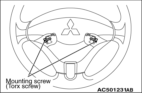
1.Remove the bag module mounting screws (Torx screws) at the sides of the steering wheel.
note Do not remove the screws from the holders.

<<D>> STEERING WHEEL REMOVAL


1.Position the steering wheel in the straight-ahead position.

2.Use special tool steering wheel puller (MB990803) to remove the steering wheel.

<<E>> CLOCK SPRING REMOVAL


warning The removed clock spring should be stored in a clean, dry place.

<<F>> PASSENGER’S (FRONT) AIR BAG MODULE REMOVAL


warning
  • When the passenger’s air bag module is removed, do not damage the engagement of the pawls.
  • The removed passenger’s air bag module should be stored in a clean, dry place with facing the deployment surface facing up.

INSTALLATION SERVICE POINTS


>>A<< PRE-INSTALLATION INSPECTION


1.
warning Dispose of air bag modules only according to the specified procedure (Refer to ).
When installing the new air bag modules and clock spring, refer to “INSPECTION” ().
2.Connect the negative battery cable.

3.
caution To prevent damage to M.U.T.-III, always turn the ignition switch to the “LOCK” (OFF) position before connecting or disconnecting M.U.T.-III.
Connect M.U.T.-III to the diagnosis connector.
4.Turn the ignition switch to the “ON” position.
5.Check diagnosis codes using M.U.T.-III to ensure that the SRS operates properly.
At this time, check that no diagnosis code except B1400 and B1410 are set.
6.
danger Wait at least 60 seconds after disconnecting the battery cable before doing any further work (Refer to ).
Turn the ignition switch to the "LOCK" (OFF) position. Disconnect the negative battery cable and tape the terminal to prevent accidental connection and air bags deployment.
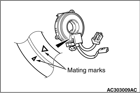
>>B<< CLOCK SPRING INSTALLATION


1.
warning Ensure that the clock spring’s mating marks are properly aligned. If not, the steering wheel may not rotate completely during a turn, or the flat cable in the clock spring could be damaged, This would prevent normal SRS operation and possibly cause serious injury to the driver.
Align the mating marks of the clock spring.
<Mating Mark Alignment>
Turn the clock spring clockwise fully. Then turn it back approximately 3 3/4 turns anticlockwise to align the mating marks.
2.Turn the front wheels to the straight-ahead position. Then install the clock spring to the column switch.

>>C<< STEERING WHEEL/AIR BAG MODULE INSTALLATION


1.
caution When installing the steering wheel, and air bag module ensure that the harness of the clock spring does not become caught or tangled.
Before installing the steering wheel, and air bag module turn the vehicle’s front wheels to the straight-ahead position and align the mating marks of the clock spring.
2.After securing the steering wheel, turn the steering wheel all the way in both directions to confirm that the steering wheel rotation is normal.

>>D<< POST-INSTALLATION INSPECTION


1.Connect the negative battery cable.
2.Turn the ignition switch to “ON” position.

3.Does the "SRS" warning lamp illuminate for approximately seven seconds, and go out?
4.If yes, the SRS system is functioning properly. If no, refer to .