|
|
If the odometer and trip meter is not displayed or all the meter needles doesn’t move, power supply to the combination meter, or the combination meter itself may be defective.
|
|
|
- Damaged harness wires and connectors
- Malfunction of the combination meter
|
|
Q.
Is the check result normal?
 Go to Step 2. Go to Step 2.
 Repair the defective connector. Repair the defective connector.
|

|
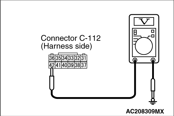
Disconnect the connector, and measure at the wiring harness side.
|
|
- Ignition switch: "LOCK" (OFF) position.
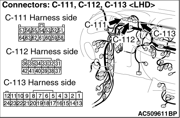
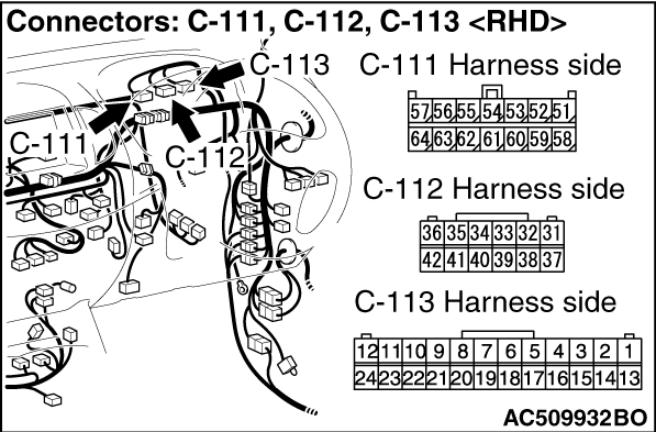
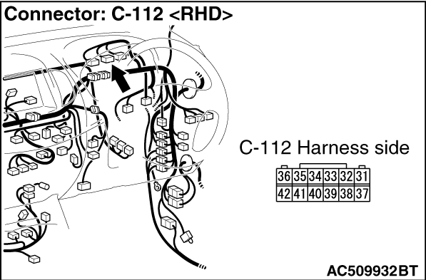
- Voltage between combination meter connector C-112 terminal No.42 and body earth.
OK: System voltage
Q.
Is the check result normal?
Go to Step 4.
Go to Step 3.
|


|
| note |
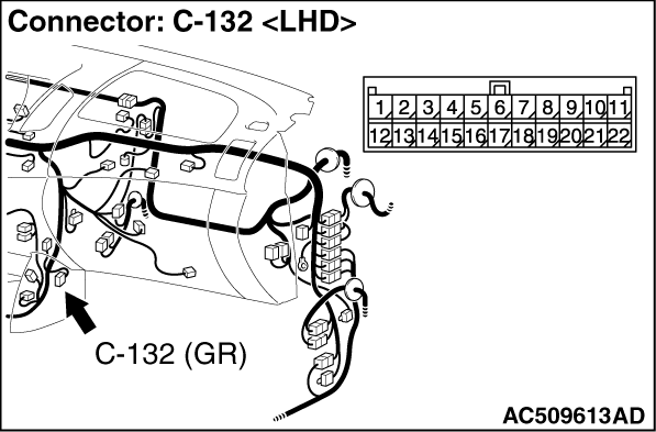
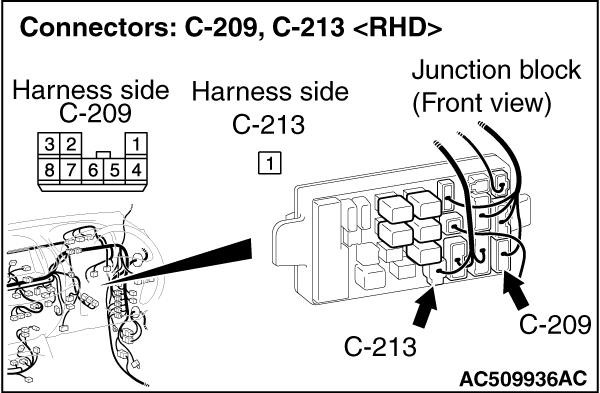
Prior to the wiring harness inspection, check joint connector C-132 and junction block connectors C-209 and C-213, and repair if necessary.
|
Q.
Is the wiring harness between the battery (fusible link No.20) and combination meter connector C-112 (terminal No.42) in good condition?
Retest the system.
Repair the wiring harness.
|
|
Disconnect the connector, and measure at the wiring harness side.
|

|
- Ignition switch: ON position.
- Voltage between combination meter connector C-112 terminal No.36 and body earth.
OK: System voltage
Q.
Is the check result normal?
Go to Step 6
Go to Step 5
|
|
| note |
Prior to the wiring harness inspection, check joint connector C-132 and junction block connectors C-207 and C-209, and repair if necessary.
|
Q.
Is the wiring harness between the ignition switch (IG1) and combination meter connector C-112 (terminal No.36) in good condition?
Retest the system.
Repair the wiring harness.
|


|
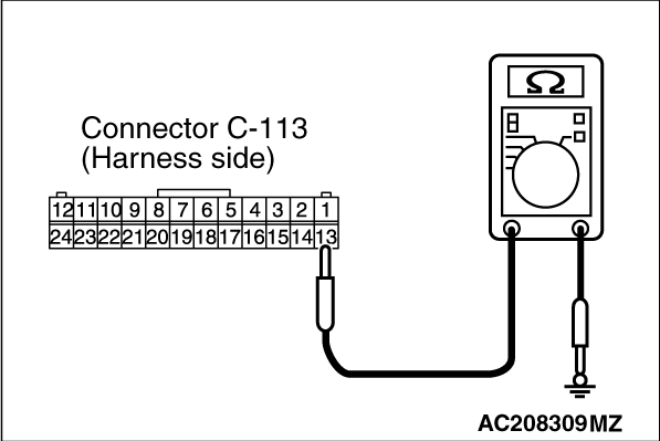
- Disconnect the connector, and measure at the wiring harness side.
- Resistance between combination meter connector C-113 terminal No.13 and body earth.
OK: Continuity exists (2 Ω or less)
|
|
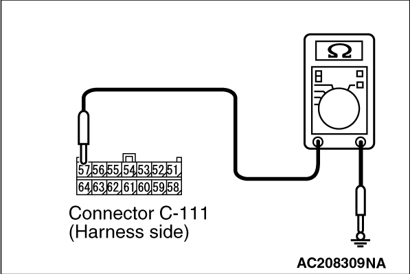
- Resistance between combination meter connector C-111 terminal No.57 and body earth.
OK: Continuity exists (2 Ω or less)
Q.
Is the check result normal?
Go to Step 8
Go to Step 7
|
|
Q.
Is the wiring harness between the combination meter connector C-111 (terminal No.57), C-113 (terminal No.13) and body earth in good condition?
Retest the system.
Repair the wiring harness.
|
|
|
Q.
Is the check result normal?
|
|
|
The trouble can be an intermittent malfunction (Refer to GROUP 00 - How to Cope with Intermittent Malfunction  ). ).
|
|
|
|
|
|
Replace the combination meter.
|
|
|
|
)
)
)
)
)
)
)
)
)
)
)
)
)
)
)
)