|
|
Using the signal check of the automatic mode in the service function, check the key position status. (Refer to  .) .)
|
|
|
OK: Normal condition is displayed.
|
|
|
Q.
Is the check result normal?
|
|
|
Use the M.U.T-III to diagnose the CAN bus lines.
|
|
|
Q.
Is the check result satisfactory?
|
|
|
 Repair the CAN bus lines (Refer to GROUP 54C, Diagnosis - Can Bus Diagnostics Table ). After diagnosing the CAN bus lines, go to Step 3. Repair the CAN bus lines (Refer to GROUP 54C, Diagnosis - Can Bus Diagnostics Table ). After diagnosing the CAN bus lines, go to Step 3.
|
|
|
|
|
|
Check whether the ETACS-ECU diagnosis code is set.
|
|
|
Q.
Is the diagnosis code set?
|
|
|
 Diagnose ETACS-ECU (Refer to ). Diagnose ETACS-ECU (Refer to ).
|
|
|
|
|
|
When the ignition switch is turned to the "LOCK" (OFF) position, check that the CAN adapter does not set the diagnosis code.
|
|
|
Q.
Is the diagnosis code set?
|
|
|
Refer to diagnosis code chart .
|
|
|
|


|
Q.
Is the check result normal?
Go to Step 6.
Repair the defective connector.
|
|
(1)Disconnect the connector, and measure at the wiring harness side.
|

|
(2)Resistance between C-110 fuel pump and gauge unit connector terminal No.4 and body earth
OK: Continuity exists (2 Ω or less)
Q.
Is the check result normal?
Go to Step 8.
Go to Step 7.
|

|
| note |
Prior to the wiring harness inspection, check joint connector C-120, and repair if necessary.
|
Q.
Is the check result normal?
Go to Step 8.
Repair the wiring harness.
|
|
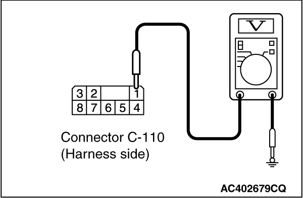
(1)Disconnect the connector, and measure at the wiring harness side.
(2)Ignition switch: ON
|
|
(3)Voltage between C-110 CAN adapter connector terminal No.1 and body earth
OK: System voltage
Q.
Is the check result normal?
Go to Step 10.
Go to Step 9.
|


|
| note |
Prior to the wiring harness inspection, check joint connector C-127, junction block connector C-207 and C-208, and repair if necessary.
|
- Check the IG (ACC) power supply open circuit.
Q.
Is the check result normal?
Retest the system.
Repair the wiring harness.
|
|
|
Check that the CAN adapter correctly when the RV meter is replaced temporarily.
|
|
|
Q.
Is the check result normal?
|
|
|
If no malfunctions are found in all steps, an intermittent malfunction is suspected. Refer to GROUP 00,How to Use Troubleshooting/Inspection Service Points - How to Cope with Intermittent Malfunction .
|
|
|
|
)
)
)
)
)
)
)
)
)
)
)