|
Q.
Is the check result normal?
 Go to Step 2. Go to Step 2.
 Repair the defective connector. Repair the defective connector.
|
|
|
Check the ambient air temperature sensor . .
|
|
|
Q.
Is the check result normal?
|
|
|
Replace the ambient air temperature sensor.
|
|
|
|
|
|
Using the monitor status of the automatic mode in the service function, check the ambient
temperature sensor status. (Refer to .)
|
|
|
OK: Normal condition is displayed.
|
|
|
Q.
Is the check result normal?
|
|
Q.
Is the check result normal?
Go to Step 5.
Repair the defective connector.
|
|
| note |
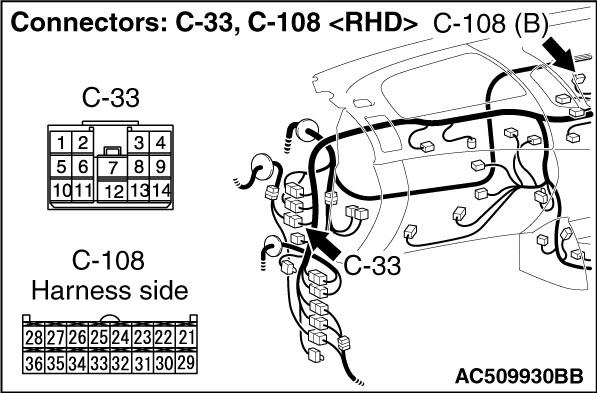
Prior to the wiring harness inspection, check intermediate connector C-33, and repair
if necessary.
|
- Check the output lines for open circuit.
Q.
Is the check result normal?
Go to Step 9.
Repair the wiring harness.
|
|
|
Check the vehicle speed signal data list of DIESEL system.
|
|
|
Item No.4: Vehicle speed sensor (Refer to GROUP 13A, Data list reference table .)
|
|
|
Q.
Is the check result satisfactory?
|
|
|
Diagnose DIESEL system (Refer to GROUP 13A , Troubleshooting ).
After diagnosing the DIESEL system.
|
|
|
|
|
Q.
Is the check result normal?
Go to Step 8.
Repair the defective connector.
|
|
| note |
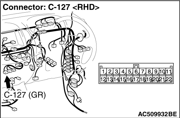
Prior to the wiring harness inspection, check the joint connector C-127 and intermediate
connector C-30, and repair if necessary.
|
- Check the input line circuit.
Q.
Is the check result normal?
Go to Step 9.
Repair the wiring harness.
|
|
|
Q.
Is a malfunction eliminated?
|
|
|
If no malfunctions are found in all steps, an intermittent malfunction is suspected.
Refer to GROUP 00, How to Use Troubleshooting/Inspection Service Points -
How
to Cope with Intermittent Malfunction .
|
|
|
|
)
)
)
)
)
)
)
)
)
)