|
| caution |
The strand end of the twist wire should be within 10 cm from the connector. For details
refer to  . .
|
|

|
When checking the joint connector, ensure that its wiring harness side and its short pins
are not damaged.
Q.
Is the check result normal?
 Go to Step 2. Go to Step 2.
 Repair the defective connector. Replace the joint connector as necessary. Repair the defective connector. Replace the joint connector as necessary.
|

|
(1)Disconnect the joint connector (CAN1) and the intermediate connector, and measure at the
wiring harness side.
(2)Turn the ignition switch to the LOCK (OFF) position.
(3)
| caution |
When measuring the resistance, disconnect the negative battery
terminal. For details refer to .
|
Ensure that the negative battery terminal is disconnected.
|

|
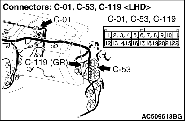
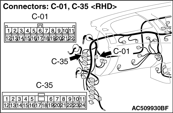
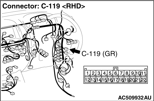
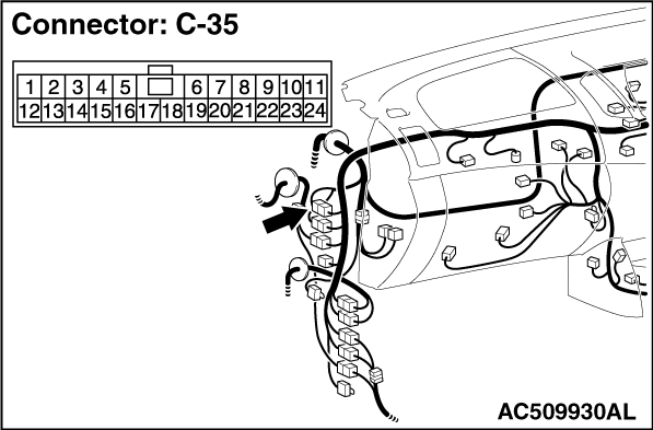
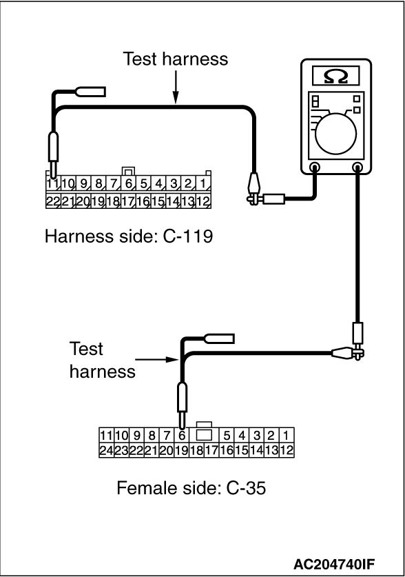
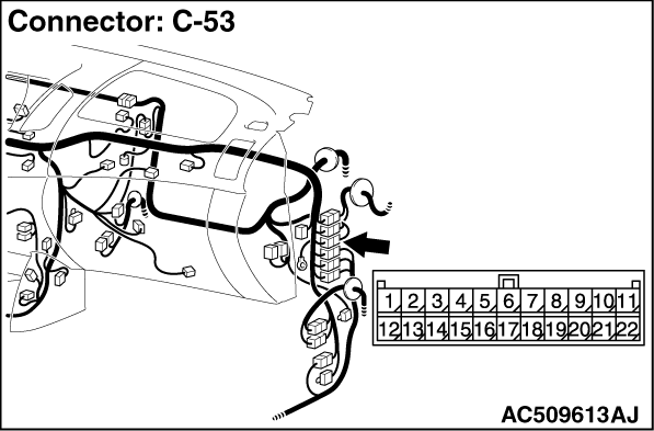
(4)Continuity between C-119 joint connector (CAN1) terminal No.11 and C-53 <LHD> or C-35 <RHD>
intermediate connector terminal No.6
OK: Continuity (2 Ω
or less)
|
|
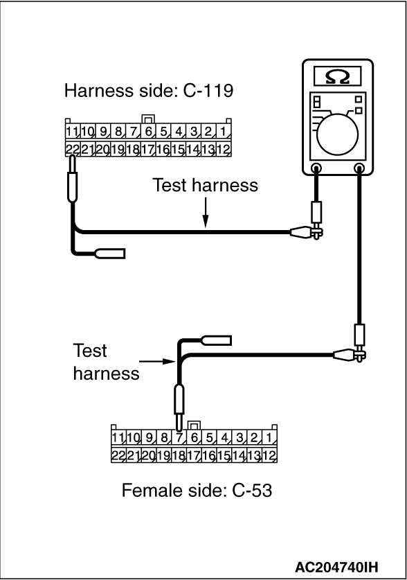
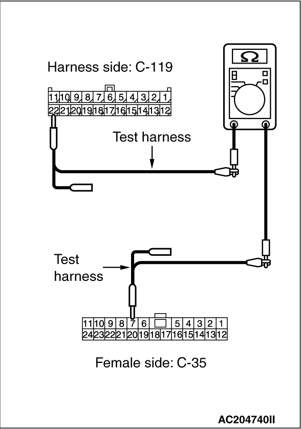
(5)Continuity between C-119 joint connector (CAN1) terminal No.22 and C-53 <LHD> or C-35 <RHD>
intermediate connector terminal No.7
OK: Continuity (2 Ω
or less)
| caution |
Strictly observe the specified wiring harness repair procedure.
For details refer to .
|
Q.
Is the check result normal?
<All the resistances measure 2 Ω
or less>
Go to Step
3 .
NO : <Either or all of the voltages measure more than 2 Ω>
Repair
the wiring harness between joint connector (CAN1) and intermediate connector (C-53 <LHD>
or C-35 <RHD>).
|

|
(1)Disconnect joint connector (CAN2) and the intermediate connector, and measure at the wiring
harness side.
(2)Turn the ignition switch to the LOCK (OFF) position.
(3)
| caution |
When measuring the resistance, disconnect the negative battery
terminal. For details refer to .
|
Ensure that the negative battery terminal is disconnected.
|

|
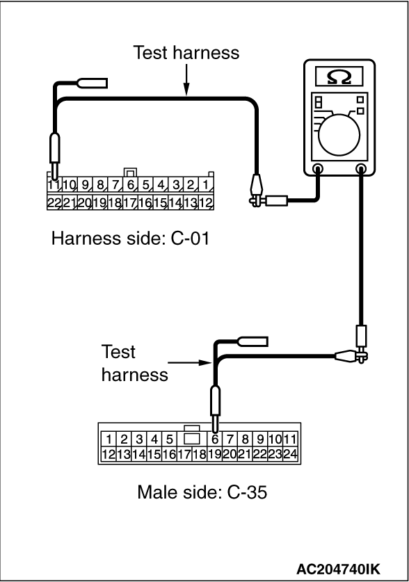
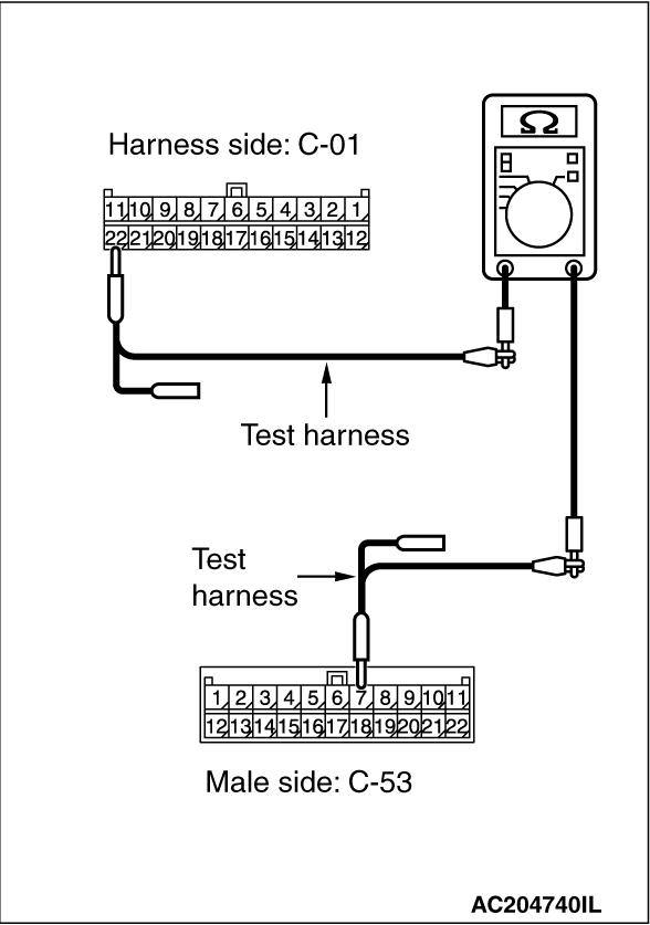
(4)Continuity between C-01 joint connector (CAN2) terminal No.11 and C-53 <LHD> or C-35 <RHD>
intermediate connector terminal No.6
OK: Continuity (2 Ω
or less)
|

|
(5)Continuity between C-01 joint connector (CAN2) terminal No.22 and C-53 <LHD> or C-35 <RHD>
intermediate connector terminal No.7
OK: Continuity (2 Ω
or less)
| caution |
Strictly observe the specified wiring harness repair procedure.
For details refer to .
|
Q.
Is the check result normal?
<All the resistances measure 2 Ω
or less>
Follow diagnosis
item 5, 6, 7, 8, 9, 10, 11, 13 and 14. Refer to .
NO : <Either or all of the voltages measure more than 2 Ω>
Repair
the wiring harness between the intermediate connector and the intermediate connector.
|
)
)
)
)
)
)
)
)
)
)
)
)
)
)
)
)
)