|
|
The blower system, the compressor system or the communication system between the engine-ECU
and the A/C-ECU may be defective if there is no cool air coming from the spit hole.
|
|
|
- Malfunction of air thermo sensor
- Malfunction of dual pressure switch
- Damaged harness wires and connectors
- Malfunction of engine-ECU
- Malfunction of the automatic A/C control panel (A/C-ECU)
|
|
|
Check that the air selection switch, rear window defogger switch and air volume control
dial can operate.
|
|
|
Q.
Is the check result normal?
|
|
|
 Inspection Procedure 9: Refer to A/C-ECU power supply system Inspection Procedure 9: Refer to A/C-ECU power supply system  . .
|
|
|
|
|
Q.
Is the check result normal?
 Go to Step 3. Go to Step 3.
Repair the connector.
|
|
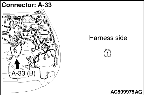
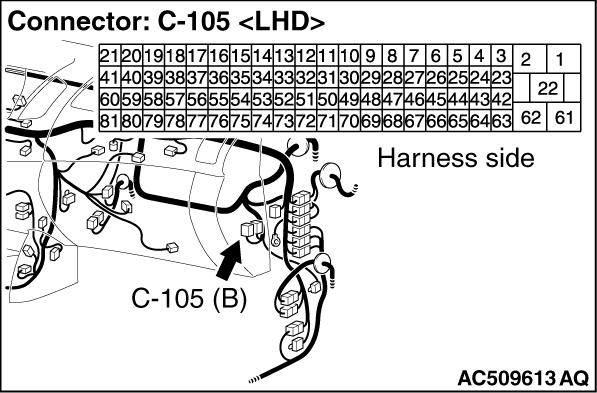
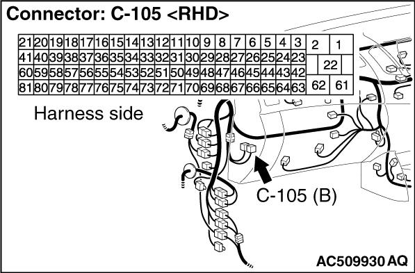
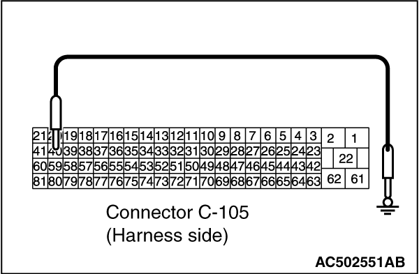
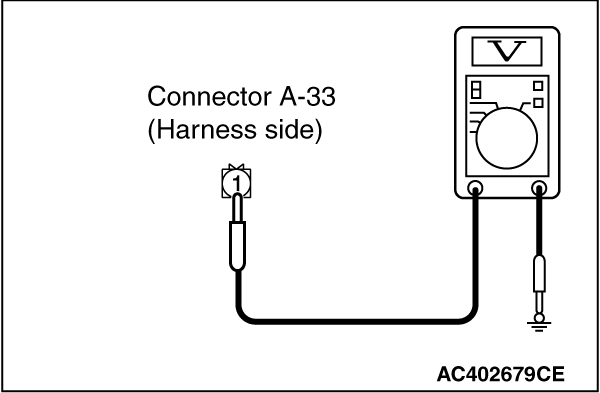
(1)Disconnect the connector, and measure at the wiring harness side.
(2)Turn the ignition switch to the "ON" position.
|
|
(3)Disconnect engine-ECU connector C-105 and earth terminal 40.
|
|
(4)Voltage between terminal 1 and body earth.
OK: System voltage
Q.
Is the check result normal?
Go to Step 4.
Refer to Inspection Procedure 5 " The compressor does not work ".
|
|
|
Check that the blower motor operates under the following conditions.
|
|
|
- ignition switch: ON
- Blower speed selection dial: MAX
|
|
|
Q.
Is the check result normal?
|
|
|
Refer to Inspection Procedure 2 " The blower does not work ".
|
|
|
|
|
Q.
Is the check result normal?
Go to Step 6.
Repair the connector.
|
|
|
Q.
Is the check result normal?
|
|
|
Replace the dual pressure switch.
|
|
|
|

|
Q.
Is the check result normal?
Go to Step 8.
Repair the connector.
|
|
- Check the input line for open circuit.
Q.
Is the check result normal?
Go to Step 9.
Repair the wiring harness.
|

|
Q.
Is the check result normal?
Go to Step 10.
Repair the connector.
|

|
| note |
Prior to the wiring harness inspection, check intermediate connector C-54, and repair
if necessary.
|
- Check the input line for open circuit.
Q.
Is the check result normal?
Go to Step 11.
Repair the wiring harness.
|

|
| note |
Prior to the wiring harness inspection, check intermediate connector A-28, and repair
if necessary.
|
- Check the input line for open circuit.
Q.
Is the check result normal?
Go to Step 12.
Repair the wiring harness.
|
|
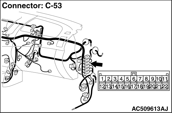
| note |
Prior to the wiring harness inspection, check intermediate connector C-53, and repair
if necessary.
|
- Check the input line for open circuit.
Q.
Is the check result normal?
Go to Step 13.
Repair the wiring harness.
|
|
|
Q.
Is the refrigerant level correct?
|
|
|
Correct the refrigerant level (Refer to On-vehicle Service .)
|
|
|
|
|
|
Check that the compressor works normally.
|
|
|
Q.
Is the check result normal?
|
|
|
This diagnosis is complete.
|
|
|
|
)
)
)
)
)
)
)
)
)
)
)
)
)
)
)