|
|
If the blower motor does not operate, the blower motor circuit system may be defective.
|
|
|
- Malfunction of the blower relay
- Malfunction of the blower motor
- Malfunction of the blower switch
- Damaged the wiring harness or connectors
|
|
|
(1)Turn the ignition switch to the "ON" position.
|
|
|
(2)Turn the blower switch to the "4 (HI) " position.
|
|
|
Q.
Does the blower motor operate when the blower switch is moved to the "4 (HI) " position?
|
|
|
 Refer to Inspection procedure 3 "The blower air volume cannot be changed Refer to Inspection procedure 3 "The blower air volume cannot be changed  ." ."
|
|
|
|

|
Q.
Is the check result normal?
Go to Step 3.
 Repair the connector. Repair the connector.
|
|
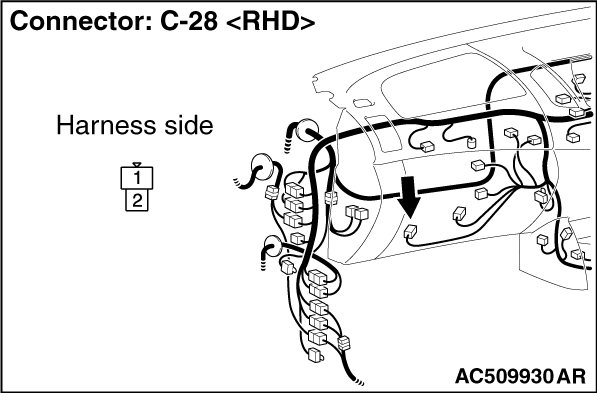
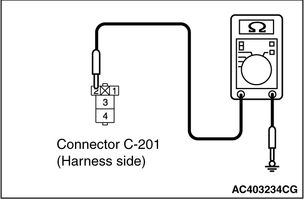
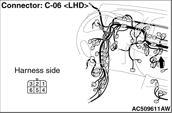
(1)Disconnect the connector, and measure at the wiring harness side.
|

|
(2)Measure the resistance between terminal 2 and body earth.
OK: Continuity (Less than 2Ω)
Q.
Is the check result normal?
Go to Step 5.
Go to Step 4.
|
|
- Check the blower motor earth line for open circuit.
Q.
Is the check result normal?
The trouble can be an intermittent malfunction (Refer to GROUP 00, How to Cope
with Intermittent Malfunction ).
Repair the wiring harness.
|
|
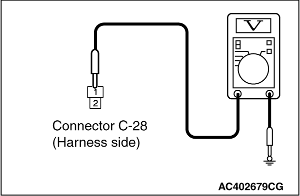
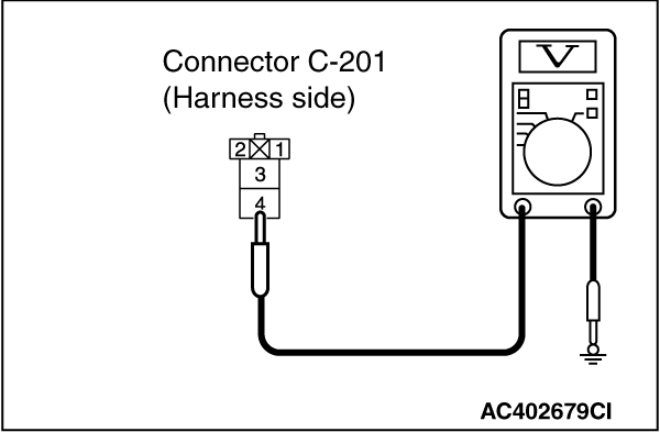
(1)Disconnect the connector, and measure at the wiring harness side.
(2)Turn the ignition switch to the "ON" position.
(3)Turn the blower switch to the "4 (HI) " position.
|
|
(4)Measure the voltage between terminal 1 and body earth.
OK: System voltage
Q.
Is the check result normal?
Go to Step 18.
Go to Step 6.
|
|
Q.
Is the check result normal?
Go to Step 7.
Repair the connector.
|
|
|
Q.
Is the blower relay continuity in good condition?
|
|
|
Replace the blower relay.
|
|
|
|
|
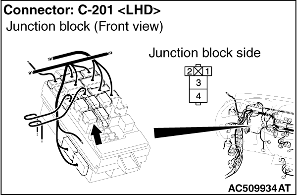
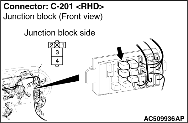
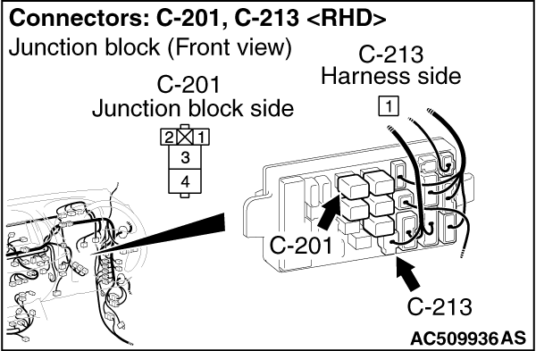
(1)Remove the relay, and measure at the junction block side.
(2)Turn the ignition switch to the "ON" position.
|

|
(3)Measure the voltage between terminal 1 and earth.
OK: System voltage
Q.
Is the check result normal?
Go to Step 10.
Go to Step 9.
|


|
| note |
Prior to the wiring harness inspection, check junction block connector C-207, and repair
if necessary.
|
- Check the blower relay power supply line for open circuit.
Q.
Is the check result normal?
The trouble can be an intermittent malfunction (Refer to GROUP 00, How to Cope
with Intermittent Malfunction ).
Repair the wiring harness.
|
|
(1)Remove the relay, and measure at the junction block side.
|
|
(2)Measure the resistance Continuity between terminal 2 and body earth.
OK: Continuity (Less than 2Ω)
Q.
Is the check result normal?
Go to Step 12.
Go to Step 11.
|

|
| note |
Prior to the wiring harness inspection, check junction block connectors C-208, and repair
if necessary.
|
- Check the blower relay earth wires for open circuit.
Q.
Is the check result normal?
The trouble can be an intermittent malfunction (Refer to GROUP 00, How to Cope
with Intermittent Malfunction ).
Repair the wiring harness.
|
|
(1)Remove the relay, and measure at the junction block side.
|
|
(2)Measure the voltage between terminal 4 and body earth.
OK: System voltage
Q.
Is the check result normal?
Go to Step 14.
Go to Step 13.
|
|
| note |
Prior to the wiring harness inspection, check junction block connector C-213, and repair
if necessary.
|
- Check the blower relay power supply line for open circuit.
Q.
Is the check result normal?
The trouble can be an intermittent malfunction (Refer to GROUP 00, How to Cope
with Intermittent Malfunction ).
Repair the wiring harness.
|

|
Q.
Is the check result normal?
Go to Step 15.
Repair the connector.
|
|
|
Q.
Is the blower switch continuity in good condition?
|
|
|
Replace the blower switch.
|
|
|
|
|
| note |
Prior to the wiring harness inspection, check junction block connector C-207, and repair
if necessary.
|
- Check the blower relay output line for open circuit.
Q.
Is the check result normal?
Go to Step 17.
Repair the wiring harness.
|
|
- Check the blower motor power supply line for open circuit.
Q.
Is the check result normal?
The trouble can be an intermittent malfunction (Refer to GROUP 00, How to Cope
with Intermittent Malfunction ).
Repair the wiring harness.
|
|
|
Q.
Is the check result normal?
|
|
|
The trouble can be an intermittent malfunction (Refer to GROUP 00, How to Cope
with Intermittent Malfunction ).
|
|
|
|
|
|
Replace the blower motor.
|
|
|
|
)
)
)
)
)
)
)
)
)
)
)
)
)
)
)
)
)
)