|
|
When the PTC heater does not work under the following conditions, the heater switch system
or the PTC heater circuit system may be defective.
|
|
|
PTC heater operating conditions
- heater switch: ON
- Air outlet: FOOT/DEF, FOOT, FACE/FOOT
- Temperature control dial: MAX HOT
- Coolant temperature: 80 degrees celsius or less
|
|
|
- Malfunction of the heater switch system
- Damaged the wiring harness or connectors
- Malfunction of the PTC heater relay 1
- Malfunction of the PTC heater relay 2
- Malfunction of the PTC heater 1
- Malfunction of the PTC heater 2
|
|
Q.
Is the check result normal?
 Go to Step 2. Go to Step 2.
 Repair the connector. Repair the connector.
|
|
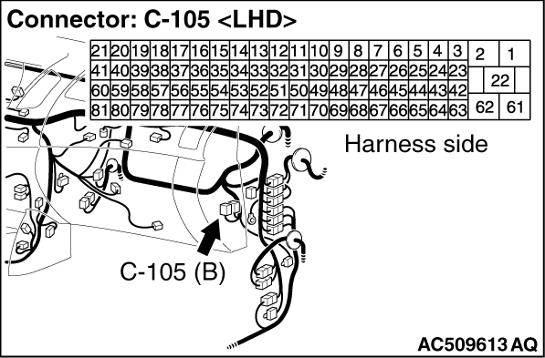
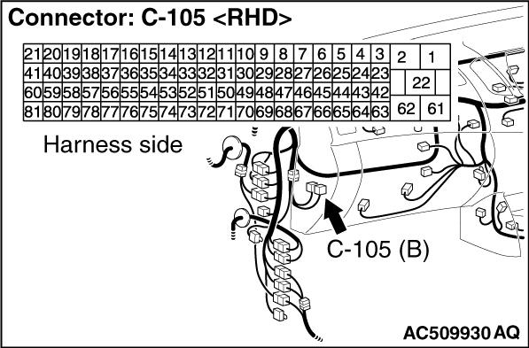
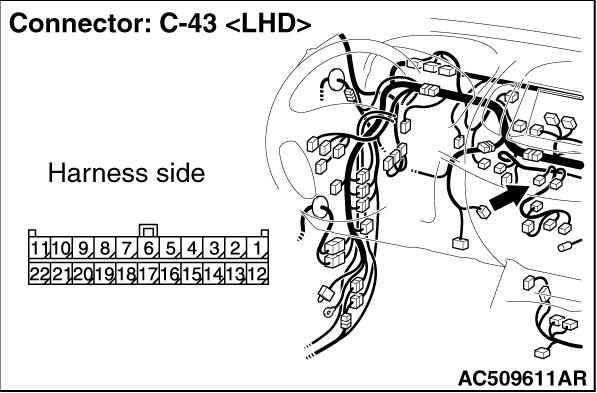
(1)Disconnect the connector, and measure at the wiring harness side.
(2)Turn the ignition switch to the "ON" position.
(3)Turn the heater switch to the "ON" position.
|

|
(4)Voltage between terminal 14 and body earth.
OK: System voltage
Q.
Is the check result normal?
Go to Step 3.
Inspection Procedure 8: Refer to heater switch system  . .
|

|
Q.
Is the check result normal?
Go to Step 4.
Repair the connector.
|
|
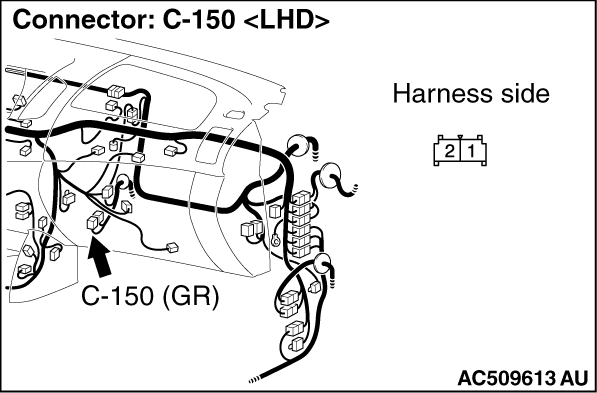
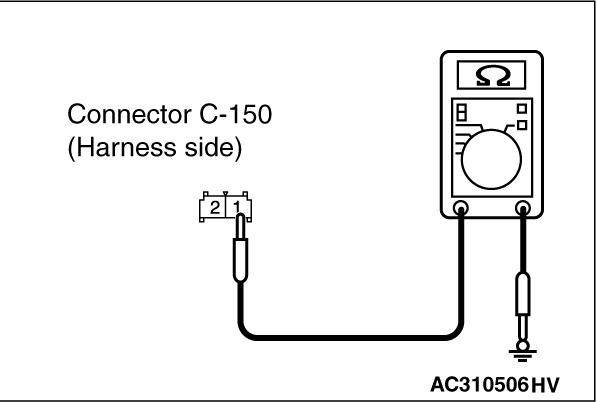
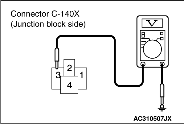
(1)Disconnect the connector, and measure at the wiring harness side.
|

|
(2)Continuity between terminal 1 and body earth
OK: Continuity (Less than 2Ω)
Q.
Is the check result normal?
Go to Step 6.
Go to Step 5.
|
|
- Check the PTC heater earth line for open circuit.
Q.
Is the check result normal?
The trouble can be an intermittent malfunction (Refer to GROUP 00, How to Cope
with Intermittent Malfunction .)
Repair the wiring harness.
|
|
(1)Disconnect the connector, and measure at the wiring harness side.
|
|
(2)Continuity between terminal 1 and body earth
OK: Continuity (Less than 2Ω)
Q.
Is the check result normal?
Go to Step 8.
Go to Step 7.
|
|
- Check the PTC heater earth line for open circuit.
Q.
Is the check result normal?
The trouble can be an intermittent malfunction (Refer to GROUP 00, How to Cope
with Intermittent Malfunction .)
Repair the wiring harness.
|
|
(1)Disconnect the connector, and measure at the wiring harness side.
(2)Turn the ignition switch to the "ON" position.
|

|
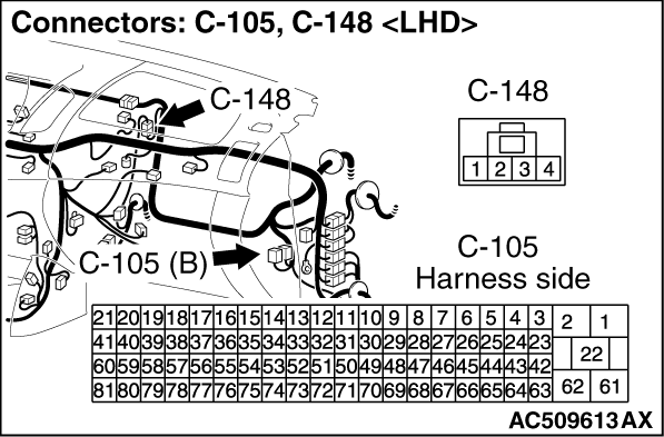
(3)Disconnect engine-ECU connector C-105 and earth terminal 38.
|

|
(4)Voltage between terminal 2 and body earth.
OK: System voltage
Q.
Is the check result normal?
Go to Step 18.
Go to Step 9.
|
|
Q.
Is the check result normal?
Go to Step 10.
Repair the connector.
|
|
|
Q.
Is the heater switch relay 1 in good condition?
|
|
|
Replace the heater switch relay 1.
|
|
|
|
|
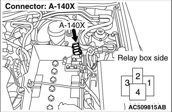
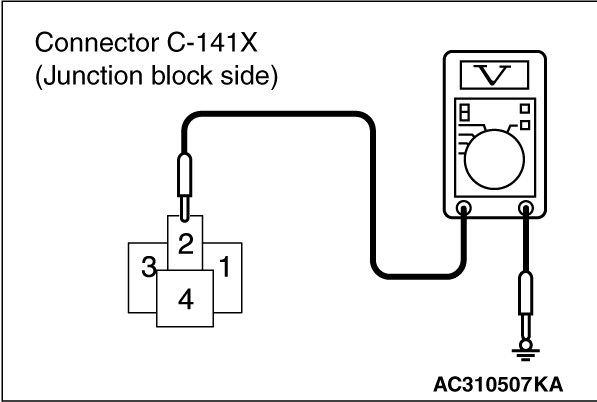
(1)Remove the relay, and measure at the relay block side.
(2)Turn the ignition switch to the "ON" position.
|
|
(3)Voltage between terminal 3 and body earth.
OK: System voltage
Q.
Is the check result normal?
Go to Step 13.
Go to Step 12.
|


|
| note |
Prior to the wiring harness inspection, check intermediate connectors C-148, A-28 and
junction block connector C-210, and repair if necessary.
|
- Check the PTC heater relay 1 earth supply line for open circuit.
Q.
Is the check result normal?
The trouble can be an intermittent malfunction (Refer to GROUP 00, How to Cope
with Intermittent Malfunction .)
Repair the wiring harness.
|
|
(1)Remove the relay, and measure at the relay block side.
|

|
(2)Voltage between terminal 2 and body earth.
OK: System voltage
Q.
Is the check result normal?
Go to Step 15.
Go to Step 14.
|
|
- Check the PTC heater relay 1 power supply line for open circuit.
Q.
Is the check result normal?
The trouble can be an intermittent malfunction (Refer to GROUP 00, How to Cope
with Intermittent Malfunction ).
Repair the wiring harness.
|
|
| note |
Prior to the wiring harness inspection, check intermediate connector C-148, and repair
if necessary.
|
- Check the PTC heater relay 1 earth line for open or short circuit.
Q.
Is the check result normal?
Go to Step 16.
Repair the wiring harness.
|
|
- Check the PTC heater relay 1 power supply line for open circuit.
Q.
Is the check result normal?
The trouble can be an intermittent malfunction (Refer to GROUP 00, How to Cope
with Intermittent Malfunction ).
Repair the wiring harness.
|
|
(1)Disconnect the connector, and measure at the wiring harness side.
(2)Turn the ignition switch to the "ON" position.
|

|
(3)Disconnect engine-ECU connector C-105 and earth terminal 41.
|

|
(4)Voltage between terminal 2 and body earth.
OK: System voltage
Q.
Is the check result normal?
Go to Step 26.
Go to Step 18.
|
|
Q.
Is the check result normal?
Go to Step 19.
Repair the connector.
|
|
|
Q.
Is the PTC heater relay 2 in good condition?
|
|
|
Replace the PTC heater relay 2.
|
|
|
|
|
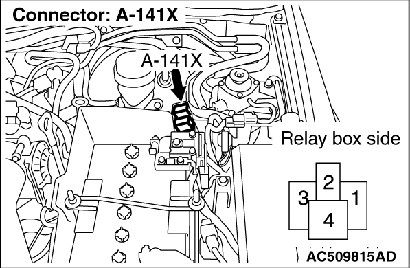
(1)Remove the relay, and measure at the relay block side.
(2)Turn the ignition switch to the "ON" position.
|

|
(3)Voltage between terminal 3 and body earth.
OK: System voltage
Q.
Is the check result normal?
Go to Step 22.
Go to Step 21.
|
|
| note |
Prior to the wiring harness inspection, check junction block connectors C-210, intermediate
connector A-28 and C-148, and repair if necessary.
|
- Check the PTC heater relay 2 power supply line for open circuit.
Q.
Is the check result normal?
The trouble can be an intermittent malfunction (Refer to GROUP 00, How to Cope
with Intermittent Malfunction .)
Repair the wiring harness.
|
|
(1)Remove the relay, and measure at the relay block side.
|
|
(2)Voltage between terminal 2 and body earth.
OK: System voltage
Q.
Is the check result normal?
Go to Step 24.
Go to Step 23.
|
|
- Check the PTC heater relay 2 power supply line for open circuit.
Q.
Is the check result normal?
The trouble can be an intermittent malfunction (Refer to GROUP 00, How to Cope
with Intermittent Malfunction ).
Repair the wiring harness.
|
|
| note |
Prior to the wiring harness inspection, check intermediate connector C-148, and repair
if necessary.
|
- Check the PTC heater relay 2 earth line for open or short circuit.
Q.
Is the check result normal?
Go to Step 25.
Repair the wiring harness.
|
|
- Check the PTC heater power supply line for open circuit.
Q.
Is the check result normal?
The trouble can be an intermittent malfunction (Refer to GROUP 00, How to Cope
with Intermittent Malfunction .)
Repair the wiring harness.
|
|
Q.
Is the check result normal?
Go to Step 27.
Repair the connector.
|

|
| note |
Prior to the wiring harness inspection, check intermediate connector C-52, and repair
if necessary.
|
- Check the A/C-ECU input line for open or short circuit.
Q.
Is the check result normal?
Go to Step 28.
Repair the wiring harness.
|
|
|
Check that the PTC heater works normally.
|
|
|
Q.
Is the check result normal?
|
|
|
This diagnosis is complete.
|
|
|
|
)
)
)
)
)
)
)
)
)
)
)
)
)
)
)
)
)
)
)
)
)
)
)
)