|
|
The following operations will be required due to the introduction of the drive belt system
with auto-tensioner.
|
|
1.
| caution |
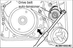
To reuse the drive belt, draw an arrow indicating the rotating
direction on the back of the drive belt using chalk to install the same direction.
|
Turn the drive belt auto-tensioner clockwise.
|
|
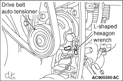
2.Insert the L-shaped hexagon wrench into the drive belt auto-tensioner hole to fix the
drive belt auto-tensioner.
3.Remove the drive belt.
|
|
1.
| caution |
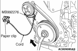
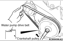
- To reuse the water pump drive belt, draw
an arrow indicating the rotating direction on the back of the water pump drive belt using chalk
to install the same direction.
- Hang the special tool drive belt remover (MB992276) on the vehicle components (including
front sidemembers) using a cord and paper clip to prevent from falling.
|
Mount the special tool drive belt remover (MB992276) in between the water pump pulley
and the water pump drive belt, then hold it with your fingers.
2.
| caution |
Be careful that the finger holding the special tool MB992276 is not pinched.
|
Slightly turn the crankshaft pulley clockwise until the special tool MB992276 is pinched
and held between the water pump pulley and the water pump drive belt.
3.If the special tool MB992276 is held, move the finger off.
4.
| caution |
If the water pump drive belt is detached, be careful
that the special tool MB992276 is also detached and fallen.
|
Slowly turn the crankshaft pulley clockwise until the water pump drive belt goes aground
on the special tool MB992276 and is detached.
5.Remove the special tool MB992276.
|
|
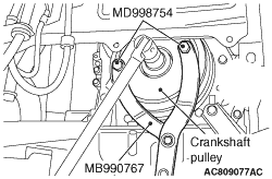
1.Use the following special tools to support the crankshaft pulley:
- Front hub and flange yoke holder (MB990767)
- Pin (MD998754)
2.Loosen the crankshaft pulley centre bolt.
|
|
|
Install a special tool for holding the engine and transmission assembly.
|
|
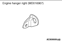
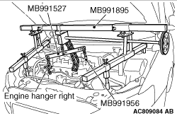
1.Install the engine hanger right (MD016967) to the cylinder head tightening bolt of the
emission control pipe and hose assembly.
|
|
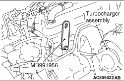
2.Install the special tool engine hanger plate (MB991956) to the cylinder head.
|
|
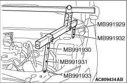
3.<When special tool engine hanger (MB991928) is used>
(1)
Assemble special tool engine hanger (MB991928). (Set the following
parts on the base hanger.)
- Slide bracket (HI)
- Joint x 2 (50) (MB991929)
- Joint x 2 (90) (MB991930)
- Joint x 2 (140) (MB991931)
- Foot x 2 (standard) (MB991932)
- Foot x 2 (short) (MB991933)
(2)
Set the foot of the special tool as shown in the figure.
|
|
| note |
Slide the slide bracket (HI) to adjust the engine hanger balance.
|
|
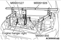
(3)
Mount special tool hanger (MB991527) to the engine hanger, and set it to special tool
MB991928 to support the engine and transmission assembly.
|
|
4.<When special tool engine hanger (MB991895) is used>
(1)
Set the foot of special tool engine hanger (MB991895) as shown in the figure.
|
|
| note |
Slide the foot to adjust the engine hanger balance.
|
|
(2)
Mount special tool hanger (MB991527) to the engine hanger, and set
it to special tool MB991895 to support the engine and transmission assembly.
|
|
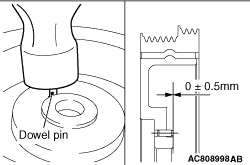
Press-fit the dowel pin to the crankshaft pulley as shown.
|
|
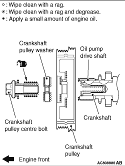
1.Wipe off the dirt on the crankshaft sprocket, crankshaft and crankshaft pulley as shown
in the figure using a rag, and then degrease the areas.
| note |
Degrease them to prevent drop in the friction coefficient of the pressed area, which is
caused by oil adhesion.
|
2.Install the crankshaft pulley.
3.Wipe off the dirt on the crankshaft pulley washer and the crankshaft pulley centre
bolt as shown in the figure using a rag.
4.Apply an adequate and minimum amount of engine oil to the threads
of the crankshaft pulley centre bolt and the lower area of the flange.
|
|
5.Use the following special tools as during removal to support the crankshaft pulley:
- Front hub and flange yoke holder (MB990767)
- Pin (MD998754)
|
|
6.Tighten the crankshaft pulley centre bolt according to the following procedure.
(1)
Tighten the crankshaft pulley centre bolt to the specified torque.
Tightening torque: 250 N·m
(2)
Loosen the crankshaft pulley centre bolt fully.
(3)
Tighten the crankshaft pulley centre bolt to the specified torque again.
Tightening torque: 110 N·m
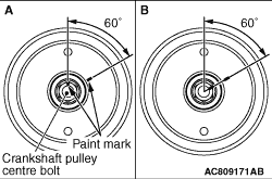
(4)
As shown in the illustration "A," apply the paint mark to the crankshaft pulley on the
extended line of the corner adjacent to the one of the crankshaft pulley centre bolt corners.
(5)
|
|
| caution |
- When the tightening angle is smaller than
the specified tightening angle, the appropriate tightening capacity cannot be secured.
- When the tightening angle is larger than the specified tightening angle, remove
the bolt to start from the beginning again according to the procedure.
|
|
Tighten the crankshaft pulley centre bolt by 60° once more. Make sure the paint
mark of crankshaft pulley centre bolt is aligned with the paint mark of crankshaft pulley as
shown in the illustration "B."
|
|
1.
| caution |
Be careful not to pinch your fingers when holding the water
pump drive belt.
|
Fit the water pump drive belt on the front step (rear three ribs) of the crankshaft pulley,
and then push the water pump drive belt at the water pump pulley side with your finger as shown.
|
|
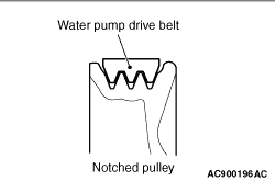
2.
| caution |
Check that the notches of the notched pulley and the notches of the water pump drive belt
are fit correctly.
|
Rotate the crankshaft pulley clockwise slowly to fit the water pump drive belt around
the water pump pulley.
|
|
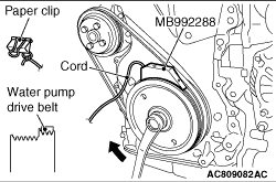
3.Set the special tool drive belt installer (MB992288) on the front side of the crankshaft
pulley. Then slide it by hand until it touches the water pump drive belt.
| note |
Hang the special tool drive belt installer (MB992288) on the vehicle components (including
front sidemembers) using a cord and paper clip to prevent from falling.
|
4.Release the special tool. Then rotate crankshaft pulley clockwise slightly until special
tool MB992288 is engaged between the water pump drive belt and the crankshaft pulley.
5.Rotate the crankshaft pulley clockwise further to fit the water pump drive belt around
the rear side of the crankshaft pulley.
6.Remove special tool MB992288.
7.Turn the crankshaft pulley clockwise on several times and check that the water pump
drive belt is installed in the water pump pulley and the crankshaft pulley securely.
|
 ).
).)
)
)
)
)
)
)
)
)
)
)
)
)
)
)
)