|
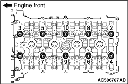
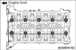
Loosen and remove the bolts in two or three steps in the order of number shown in the
figure.
|
|
1.
| caution |
The thickness of the original cylinder head gasket is selected
according to the protrusion amount of the piston. Therefore, if the cylinder block, piston,
connecting rod or crankshaft is replaced, the protrusion amount may be changed. Always select
a correct gasket by measuring the protrusion amount. (Refer to GROUP 11F - Cylinder
Head and Valves  ). ).
|
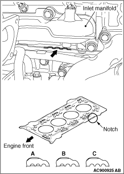
To replace the cylinder head gasket only, select a gasket of correct specification according
to the table below.
|
|
Notch specification
|
Fitted thickness mm
|
A
|
1.30 ± 0.04
|
B
|
1.35 ± 0.04
|
C
|
1.40 ± 0.04
|
|
|
|
2.
| caution |
Do not allow any foreign materials get into the coolant passages, oil
passages and cylinder.
|
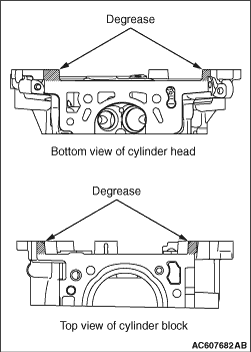
Wipe off the sealant and grease on the top surface of the cylinder block and the bottom
surface of the cylinder head, and degrease the surface where the sealant is applied.
|
|
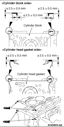
3.Apply the sealant to the top surface of the cylinder block as shown.
Specified sealant: ThreeBond 1217G or equivalent
4.Install the cylinder head gasket to the cylinder block.
| note |
- Install the cylinder head gasket immediately after the application of sealant.
- When the cylinder head gasket is installed to the cylinder block, check that the
sealant is securely applied to the bead line of the cylinder head gasket.
|
5.Apply the sealant to the top surface of the cylinder head gasket as shown.
Specified sealant: ThreeBond 1217G or equivalent
6.
| caution |
After the installation, until a sufficient period of
time (one hour or more) elapses, do not apply the engine oil or water to the sealant application
area or start the engine.
|
Install the cylinder head assembly.
|
|
|
1.Replace the cylinder head bolt and washer assembly with new ones.
|
|
|
2.Apply a small amount of engine oil to the thread of the bolts and to the washers.
|
|
3.Tighten the cylinder head bolts by the following procedure (plastic region angular tightening
method).
(1)
Tighten the cylinder head bolts to the specified torque in the order shown in the
figure in two or three steps.
Tightening torque: 50 ± 2 N·m
(2)
|
|
| caution |
- When the tightening angle is smaller than
the specified tightening angle, the appropriate tightening capacity cannot be secured.
- When the tightening angle is larger than the specified tightening angle, remove
the bolt to start from the beginning again according to the procedure.
|
|
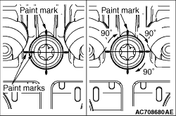
Apply paint marks to the head of cylinder head bolt and the cylinder head.
(3)
Tighten the cylinder head bolt in a 90° according to the tightening order.
(4)
Tighten the cylinder head bolt in a 90° according to the tightening order.
Check that the paint mark on the cylinder head bolt and the paint mark on the cylinder head
are on a linear line.
(5)
Loosen the cylinder head bolt fully.
(6)
Tighten the cylinder head bolt to the specified torque again in the order shown in
the figure.
Tightening torque: 50 ± 2 N·m
(7)
Tighten the cylinder head bolt in a 90° according to the tightening order.
(8)
Tighten the cylinder head bolt in a 90° according to the tightening order.
(9)
Tighten the cylinder head bolt in a 90° according to the tightening order.
Check that the paint mark on the cylinder head bolt and the paint mark on the cylinder head
are at an angle of 270°.
|
)
)
)
)
)
)
)