|
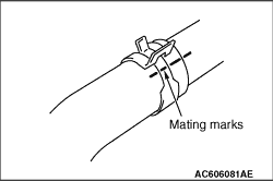
1.Make mating marks on the radiator hose and the hose clip as shown to install them in the
original position.
|
|
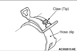
2.Break off the tip of hose clip claw and spread out the hose clip, then disconnect the
radiator lower hose.
| note |
If there is a hose clip claw, the hose clip cannot spread to capacity because the claw
contacts the hose clip.
|
|
|
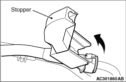
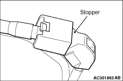
1.Remove the stopper of the fuel high-pressure hose.
|
|
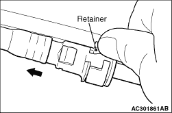
2.Raise the retainer of the fuel high-pressure hose and pull out the fuel high-pressure
hose in the direction shown in the figure.
| note |
If the retainer is released, install it securely after removing the fuel high-pressure
hose.
|
|
|
|
1.Temporarily install the engine oil pan which was removed at the valve timing chain
removal (Refer to  ). ).
|
|
|
2.
| caution |
When supporting the engine and transmission assembly with
a garage jack, be careful not to deform the engine oil pan.
|
Place a garage jack against the engine oil pan with a piece of wood in between to support
the engine and transmission assembly.
|
|
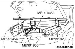
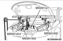
3.Remove special tool engine hanger (MB991928 or MB991895) which was installed for supporting
the engine and transmission assembly when the valve timing chain was removed.
| caution |
Be careful not to drop the camshaft bearing.
|
|
|
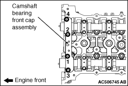
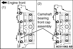
Loosen the camshaft bearing front cap mounting bolts in the order of number shown in the
figure, and remove the camshaft bearing front cap assembly.
|
|
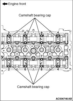
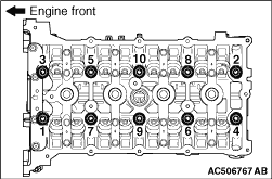
Loosen the camshaft bearing caps mounting bolts in the order of number shown in the figure
in four or five steps, and remove the camshaft bearing caps.
|
|
Loosen and remove the bolts in two or three steps in the order of number shown in the
figure.
|
|
1.
| caution |
Do not allow any foreign materials get into the coolant passages, oil
passages and cylinder.
|
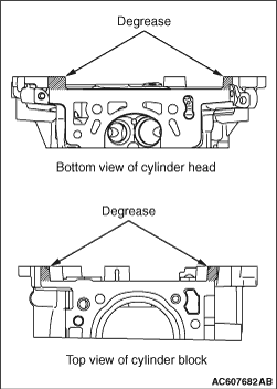
Wipe off the sealant and grease on the top surface of the cylinder block and the bottom
surface of the cylinder head, and degrease the surface where the sealant is applied.
|
|
2.Apply the sealant to the top surface of the cylinder block as shown.
Specified sealant: Three bond 1217G or equivalent
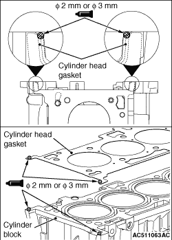
3.Install the cylinder head gasket to the cylinder block.
| note |
- Install the cylinder head gasket immediately after the application of sealant.
- When the cylinder head gasket is installed to the cylinder block, check that the
sealant is securely applied to the bead line of the cylinder head gasket.
|
4.Apply the sealant to the top surface of the cylinder head gasket as shown.
Specified sealant: Three bond 1217G or equivalent
5.
| caution |
After the installation, until a sufficient period of time (one hour or
more) elapses, do not apply the engine oil or water to the sealant application area or start
the engine.
|
Install the cylinder head assembly.
|
|
|
1.Replace a cylinder head bolts with a new one.
|
|
|
2.For two bolts of the timing chain side, the washer can be removed from the bolt. Install
the washer, with its sag facing upward, to the bolts.
|
|
|
3.Apply a small amount of engine oil to the cylinder head bolt threads and the washers.
|
|
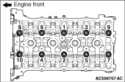
4.Tighten the cylinder head bolts by the following procedure (plastic region angular tightening
method).
(1)
Tighten the cylinder head bolts to the specified torque in the order shown in the
figure in two or three steps.
Tightening torque: 35 ± 2 N·m
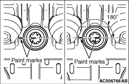
(2)
|
|
| caution |
- The cylinder head bolt
is not tightened sufficiently if the tightening angle is less than a 180 degrees angle.
- If the tightening angle exceeds the standard specification, remove the cylinder
head bolt and repeat the installation steps from Step 1.
|
|
Put a paint mark on the cylinder head bolt head and cylinder head, tighten to 180 ± 2
degrees in the order shown in the figure, and check that the paint mark on the cylinder head
bolt head aligns with the paint mark on the cylinder head.
|
|
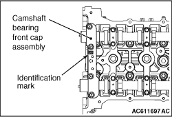
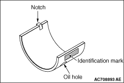
When replacing the camshaft bearing, select a camshaft bearing in relevant size according
to the camshaft bearing front cap identification mark in the table below. Identification mark
of the camshaft bearing is painted in the position shown in the figure.
|
|
Camshaft
|
Camshaft bearing identification mark
|
Identification mark
|
Journal diameter mm
|
1
|
40.000 - 40.008
|
1
|
2
|
40.008 - 40.016
|
2
|
3
|
40.016 - 40.024
|
3
|
|
|
|
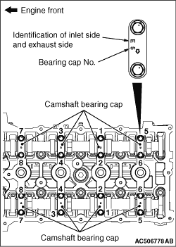
1.Install the camshaft bearing caps to the cylinder head.
| note |
Because the camshaft bearing thrust cap and camshaft bearing cap are the same in shape,
check the bearing cap number and additionally its symbol to identify the inlet and exhaust sides
for correct installation.
|
2.Tighten each camshaft bearing cap mounting bolts to the specified torque in the order
of number shown in the figure in two or three steps.
Tightening torque: 12 ± 1 N·m
|
|
1.
| caution |
When the mounting bolts are tightened with the camshaft bearing front
cap tilted, the camshaft bearing front cap is damaged. Install the camshaft bearing front cap
properly to the cylinder head and camshaft.
|
Install the camshaft bearing front cap to the cylinder head, and temporarily tighten the
camshaft bearing front cap mounting bolts to the specified torque in the order shown in the
figure (1).
Tightening torque: 17 ± 3 N·m
2.Tighten the camshaft bearing front cap mounting bolts to the specified torque again
in the order shown in the figure (2).
Tightening torque: 30 ± 2 N·m
|
|
3.Install special tool engine hanger (MB991928 or MB991895) which was installed for supporting
the engine and transmission assembly when the valve timing chain was removed (Refer to ).
4.Remove the garage jack which supports the engine and transmission assembly.
5.Remove the engine oil pan installed temporarily.
|
|
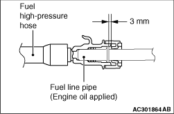
Apply a small amount of engine oil to the fuel line pipe, and install
the fuel high-pressure hose.
|
|
|
1.
| caution |
Never reuse the hose clip whose claw is broken off to prevent
the rusting.
|
Make mating mark on a new hose clip in the same position as the remove one.
|
|
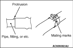
2.Insert the radiator hose until the protrusion of the pipe.
3.Align the mating marks on the radiator hose and hose clip.
4.Remove the hose clip claw and shorten the hose clip, then install the radiator hose.
|
)
)
)
)
)
)
)
)
)
)
)
)
)
)
)
)
)
)
)
)
)
)