|
|
When removing the crankshaft pulley, slightly loosen the water pump pulley mounting bolts
before removal of the alternator and others belt.
|
|
|
Install a special tool for holding the engine and transmission assembly.
|
|
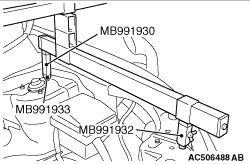
1.<When special tool engine hanger (MB991928) is used>
(1)
Assemble special tool engine hanger (MB991928) (Set the following
parts on the base hanger).
- Slide bracket (HI)
- Foot x 2 (standard) (MB991932)
- Foot x 2 (short) (MB991933)
- Joint x 2 (90) (MB991930)
(2)
Set the foot of the special tools (MB991930, MB991932 and MB991933) as shown in the figure.
|
|
| note |
Slide the slide bracket (HI) to adjust the engine hanger balance.
|
|
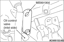
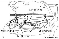
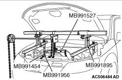
(3)
Install special tool engine hanger plate (MB991956) to the cylinder head, and set special
tool hanger (MB991527) and the chains of special tool engine hanger balancer (MB991454) to the
engine assembly to hold the engine and transmission assembly.
|
|
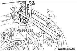
2.<When special tool engine hanger (MB991895) is used>
(1)
|
|
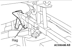
| caution |
Place a rag between special tool engine hanger (MB991895) and the windshield
to prevent the special tool (MB991895) from interfering with the windshield.
|
|
Set the foot of special tool engine hanger (MB991895) as shown in the figure.
|
|
| note |
Slide the foot to adjust the engine hanger balance.
|
|
(2)
Install special tool engine hanger plate (MB991956) to the cylinder head,
and set special tool hanger (MB991527) and the chains of special tool engine hanger balancer
(MB991454) to the engine assembly to hold the engine and transmission assembly.
|
|
1.
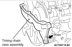
| caution |
If the adhesive strength of sealant on the timing chain
case assembly is so strong that the boss may be damaged by peeling off, do not peel it off forcibly.
|
After removing the timing chain case assembly mounting bolts, slightly pry the boss of
the timing chain case assembly shown in the figure using a flat-tipped screwdriver, and remove
the timing chain case assembly from the cylinder head and cylinder block.
|
|
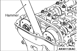
2.If the sealant cannot be peeled off easily, insert a wooden hammer shank into the timing
chain case assembly inside as shown in the figure, pry slightly, and remove the timing chain
case assembly from the cylinder head and cylinder block.
|
|
|
1.Temporarily install the crankshaft pulley to the crankshaft.
|
|
2.
| caution |
Turn the crankshaft clockwise.
|
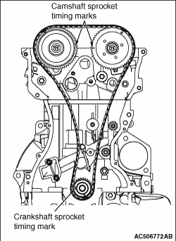
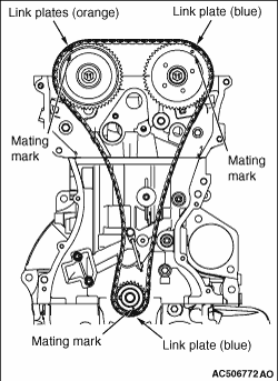
Turn the crankshaft clockwise to align the sprocket timing marks as shown in the figure
and set the cylinder No. 1 to the top dead centre of compression.
| note |
At this time, it is not necessary that the link plate (orange or blue) of the valve timing
chain always aligns with each sprocket timing mark.
|
3.Remove the crankshaft pulley installed temporarily.
|
|
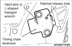
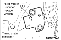
4.Using a precision flat-tipped screwdriver, release the ratchet of timing chain tensioner.
5.Compress the plunger of timing chain tensioner and insert hard wire (such as the piano
wire) or the L-shaped hexagon wrench (1.5 mm) to fix the plunger of the timing chain tensioner.
6.Remove the timing chain tensioner.
|
|
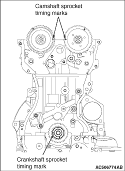
1.Set the timing marks of the camshaft sprockets and the crankshaft sprocket as shown in
the figure.
|
|
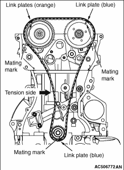
2.Align each sprocket timing chain mating mark with the link plate (orange or blue) of valve
timing chain to avoid slack of the valve timing chain tension side, and install the valve timing
chain to the sprockets.
|
|
1.Check that the sprocket timing chain mating marks align with the link plates (orange or
blue) of the valve timing chain, and install the timing chain tensioner to the cylinder block.
|
|
2.Remove the hard wire or L-shaped hexagon wrench fixing the plunger of the timing chain
tensioner to apply tension to the valve timing chain.
|
|
|
1.Apply a small amount of engine oil to the entire inner diameter of the crankshaft
front oil seal lip.
|
|
2.
| caution |
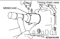
When installing the crankshaft front oil seal, be careful
to avoid damage to the crankshaft front oil seal.
|
Using special tool bush remover and installer base (MB991448), press in the crankshaft
front oil seal up to the chamfered surface of timing chain case.
|
|
|
1.
| caution |
- Be sure to remove the sealant inside
the mounting holes and the O-ring grooves.
- After degreasing with degreasing agent, check that there is no oil on the surface
where the sealant is applied.
- After degreasing with degreasing agent, never touch the degreased area with fingers.
|
Remove sealant from the timing chain case assembly and the timing chain case assembly
mounting surface of the cylinder block and the cylinder head, and degrease the surface where
the sealant is applied.
|
|
|
2.Remove all the sealant adhering to the gasket between the cylinder head and cylinder
block (three-surface aligned part.) Then, degrease the surfaces.
|
|
|
3.As for the three-surface aligned part that is indicated in step 2 above, the engine
oil oozes from the cylinder head gasket. Thus, quickly apply the sealant to it after degreasing.
|
|
|
4.
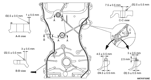
Apply a bead of the sealant to the timing chain case assembly mounting surface. The bead
diameter should be 2.5 ± 0.5 mm. Overlap the part "A" with the diameter of 4.5 ± 0.5
mm or 2.5 ± 0.5 mm as shown in the figure, and apply the sealant.
Specified sealant: Three bond 1217G or equivalent
|
|
|
5.
| caution |
- If the sealant contacts
any other part during installation of the timing chain case assembly, apply sealant again before
installing the timing chain case assembly.
- After the installation, until a sufficient period of time (one hour or more) elapses,
do not apply the oil or water to the sealant application area or start the engine.
|
Install the timing chain case assembly to the cylinder block and cylinder head so that
the sealant does not contact other parts.
| note |
Install the timing chain case assembly immediately after applying sealant.
|
|
|
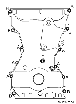
6.Insert the bolts to the timing chain case assembly as shown, and tighten them to the specified
torque.
|
|
Name
|
Symbol
|
Quantity
|
Size mm (D × L)
|
Flange bolt
|
A
|
6
|
M6 × 25
|
B
|
6
|
M8 × 30
|
Bolt
|
C
|
1
|
M6 × 25
|
|
| note |
D: Nominal diameter, L: Nominal length
|
Tightening torque:
A, C: 10 ± 2 N·m
B: 24 ± 4 N·m
|
|
|
Temporarily tighten the water pump pulley mounting bolts. Then, tighten them to the specified
torque after the installation of alternator and others belt.
|
|
|
Tightening torque: 9.0 ± 1.0 N·m
|
 ).
).)
)
)
)
)
)
)
)
)
)
)
)
)
)
)
)
)
)