|
|
1.Temporarily install the crankshaft pulley to the crankshaft.
|
|
2.
| caution |
Never turn the crankshaft anti-clockwise.
|
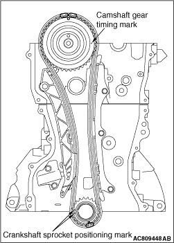
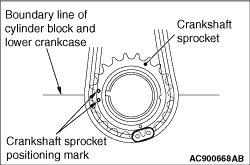
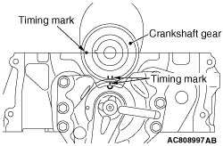
Turn the crankshaft clockwise to align the sprocket timing marks as shown in the figure
and set the No. 1 cylinder to the top dead centre of compression.
| note |
At this time, it is not necessary that the link plate (blue) of the valve timing chain
always aligns with each sprocket timing mark.
|
3.Remove the crankshaft pulley installed temporarily.
|
|
4.
| warning |
If the timing chain tensioner set pin (fixed wire) suddenly
comes off the timing chain tensioner, it is very dangerous because the plunger jumps out.
|
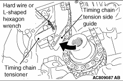
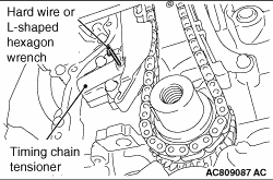
Compress the plunger of timing chain tensioner and insert hard wire (such as the piano
wire) or the L-shaped hexagon wrench (1.0 mm) to fix the plunger of the timing chain tensioner.
5.Remove the timing chain tensioner.
|
|
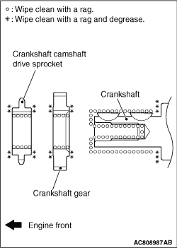
1.After wiping off the dirt on the crankshaft gear as shown in the figure using a rag, degrease
the areas.
| note |
Degrease them to prevent drop in the friction coefficient of the pressed area, which is
caused by oil adhesion.
|
|
|
2.Set the timing marks of the crankshaft gear as shown in the figure.
|

|
3.Apply an adequate and minimum amount of engine oil to the area shown in the figure of
the cam idler gear thrust plate.
|
|
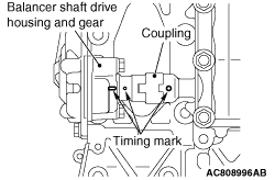
4.Align the timing marks on the balancer shaft, balancer shaft drive housing, and gear assembly
to the position shown in the figure, then install the balancer shaft drive housing and gear
assembly.
|
|
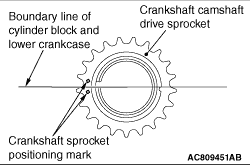
1.After wiping off the dirt on the crankshaft camshaft drive sprocket as shown in the figure
using a rag, degrease the areas.
| note |
Degrease them to prevent drop in the friction coefficient of the pressed area, which is
caused by oil adhesion.
|
|
|
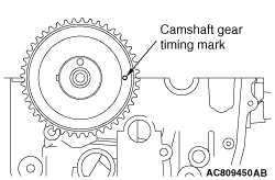
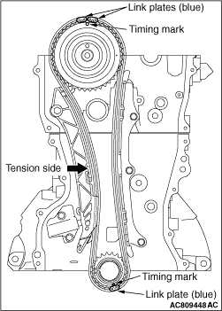
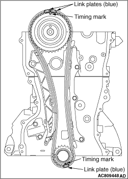
2.Set the timing marks of the camshaft sprockets and the crankshaft sprocket as shown in
the figure.
|
|
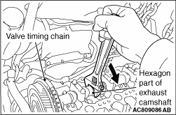
3.Set the tool onto the hexagon part of the camshaft, and turn it clockwise to avoid slack
of the chain tension side.
|
|
4.Align the timing chain mating mark on each sprocket with the link plate (blue) of valve
timing chain, and install the valve timing chain to each sprocket.
|
|
1.Check that the sprocket timing chain mating marks align with the link plates (blue) of
the valve timing chain, and install the timing chain tensioner to the cylinder block.
|
|
2.
| warning |
If the timing chain tensioner set pin (fixed wire) suddenly
comes off the timing chain tensioner, it is very dangerous because the plunger jumps out.
|
Remove the hard wire or L-shaped hexagon wrench fixing the plunger of the timing chain
tensioner to apply tension to the valve timing chain.
|
 ).
).)
)
)
)
)
)
)
)
)
)
)
)
)
)