|
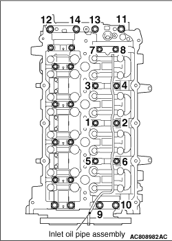
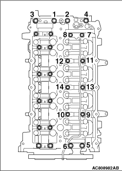
Loosen the camshaft bearing cap mounting bolts in the order of number shown in the figure
in four or five steps, and remove the camshaft bearing caps.
|
|
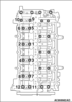
Loosen the camshaft bearing cap mounting bolts in the order of number shown in the figure
in four or five steps, and remove the camshaft bearing caps.
|
|
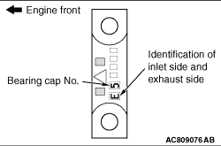
1.Install the camshaft bearing caps to the cylinder head.
| note |
Because the camshaft bearing thrust cap and camshaft bearing cap are the same in shape,
check the bearing cap number and additionally its symbol to identify the inlet and exhaust sides
for correct installation.
|
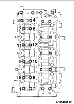
2.Tighten each camshaft bearing cap mounting bolt to the specified torque in the order
of number shown in the figure in two or three steps.
Tightening torque:
M6: 11 ± 1 N·m
M8: 20 ± 1 N·m
|
|
|
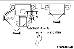
1.Completely remove the sealant adhered to camshaft bearing rear cap and the cylinder
head installation side of the camshaft bearing rear cap, and degrease them with the volatile
degreasing agent.
|
|
2.
| caution |
- Remove the excessive sealant at the supply pump assembly
mounting hole and the vacuum pump assembly mounting hole using a rag or the like.
- After the installation, until a sufficient period of time (one hour or more) elapses,
do not apply the engine oil or water to the sealant application area or start the engine.
|
Apply the sealant with a diameter of 2 mm to the camshaft bearing rear cap as shown in
the figure.
Specified sealant: ThreeBond 1217G or equivalent
| note |
Install the camshaft bearing rear cap immediately after applying sealant.
|
|
|
3.Install the camshaft bearing caps to the cylinder head.
| note |
Because the camshaft bearing thrust cap and camshaft bearing cap are the same in shape,
check the bearing cap number and additionally its symbol to identify the inlet and exhaust sides
for correct installation.
|
4.Tighten each camshaft bearing cap mounting bolt to the specified torque in the order
of number shown in the figure in two or three steps.
Tightening torque:
M6: 11 ± 1 N·m
M8: 20 ± 1 N·m
|
 ).
).)
)
)
)
)
)
)