|
|
1.Temporarily install the engine oil pan which was removed at the timing chain removal.
|
|
|
2.
| caution |
When supporting the engine and transmission assembly with
a garage jack, be careful not to deform the engine oil pan.
|
Place a garage jack against the engine oil pan with a piece of wood in between to support
the engine and transmission assembly.
|
|
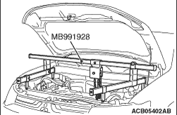
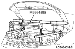
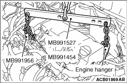
3.Remove the following special tools for holding the engine assembly, which have been attached
when the timing chain case assembly was removed.
- Engine hanger (MB991928 or MB991895)
- Hanger (MB991527)
4.Remove the V.V.T. sprocket, rocker arm and camshaft assembly (Refer to  ). ).
|
|
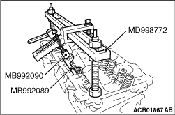
1.Screw in special tool retainer holder attachment (MB992090) to special tool valve spring
compressor (MD998772), and assemble special tool retainer holder C (MB992089).
2.
| caution |
When removing the valve spring retainer lock, leave the piston
of the cylinder in the TDC (Top Dead Centre) position. The valve may fall into the cylinder
if the piston is not properly in the TDC position.
|
Install special tool MD998772 (with special tools MB992090 and MB992089 attached) to the
cylinder head and compress the valve spring. Then, remove the valve spring retainer lock.
|
|
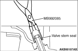
Use special tool valve stem seal pliers (MB992085) to nip the base of the stem seal (where
the outside diameter is larger) securely, and remove it by twisting it to the left and right.
|
|
|
1.
| caution |
- The valve stem seal
must not be reused.
- Do not damage the tappet wall during assembly.
- Be sure to use a special tool to install the valve stem seal. Poor installation
causes oil loss via valve guides.
- If oil is not applied, the valve stem seal may rise to the surface after it is press
fitted.
|
Apply a small amount of engine oil to the press-fit part and lip part of the new valve
stem seal.
|
|
|
2.Use a special tool to install the valve stem seal, obeying the following procedures.
|
|
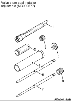
3.Special tool valve stem seal installer adjustable (MB992677) is composed of the components
shown in the illustration.
1: Chuck
2: Sleeve
3: Rock nut (small)
4: Outer pipe
5: Rock nut (large)
6: Guide pin (5.9)
7: Guide pin (4.9)
8: Cap
|
|
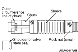
4.Adjust the inside chuck diameter, obeying the following procedures.
(1)
Install the sleeve to the chuck as shown in the illustration.
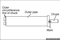
(2)
Install the shoulder of the valve stem seal to the chuck, aligning with the outer
circumference line of the chuck as shown in the illustration.
(3)
Turn the sleeve to wring the chuck.
(4)
Stop the sleeve at the position where you can easily remove the valve stem seal by
hand.
(5)
Use the (small) rock nut to fix the sleeve.
|
|
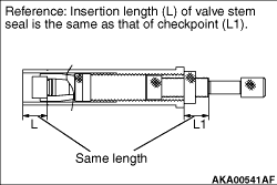
5.Adjust the stem seal insertion length, obeying the following procedures.
(1)
The position, in which the end face of the outer pipe is aligned with the outer circumference
line of the chuck, is 0 mm of the insertion length. Insert the chuck and the sleeve into the
outer pipe to fit the nut as shown in the illustration.
(2)
Turn the chuck to adjust the valve stem seal insertion length.
|
|
| note |
The insertion length can change by 1 mm per the chuck turn.
To easily know how many times the chuck is turned, put the mark at the position shown
in the illustration.
|
|
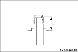
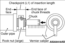
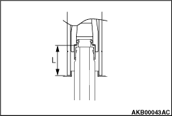
(3)
Use a vernier caliper to measure the checkpoint (L1) of the insertion length shown in
the illustration. Check the insertion length.
- Inlet side: 16.8 mm
- Exhaust side: 21.4 mm
(4)
Use the (large) rock nut to fix the sleeve.
|
|
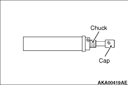
6.Install the cap to the chuck.
7.Apply the engine oil to the valve stem seal to set the chuck.
8.Install the valve spring seat.
|
|
9.Use the plastic hammer to insert the valve stem seal.
|
|
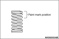
Install the inlet valve spring so that its painted side faces the rocker arm side.
| note |
The exhaust valve springs can be fitted either way up.
|
|
|
In the same manner as removal, use special tool valve spring compressor (MD998772) with
special tool retainer holder attachment (MB992090) and special tool retainer holder C (MB992089)
attached to compress the valve spring, and install the valve spring retainer lock.
|
|
|
1.Install the V.V.T. sprocket, rocker arm and camshaft assembly (Refer to ).
|
|
|
2.Attach the special tool for holding the engine assembly as during removal.
|
|
|
3.Remove the engine oil pan installed temporarily.
|
)
)
)
)
)
)
)
)
)
)
)
)
)
)
)