|
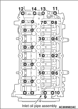
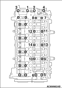
Loosen the camshaft bearing cap mounting bolts in the order of number shown in the figure
in four or five steps, and remove the camshaft bearing caps.
|
|
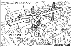
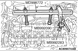
1.Screw in special tool retainer holder attachment (MB992090) to special tool valve spring
compressor (MD998772), and assemble special tool retainer holder D (MB992283).
2.
| caution |
When removing the valve spring retainer lock, leave the piston
of the cylinder in the TDC (Top Dead Centre) position. The valve may fall into the cylinder
if the piston is not properly in the TDC position.
|
Install special tool MD998772 (with special tools MB992090 and MB992283 attached) to the
cylinder head and compress the valve spring. Then, remove the valve spring retainer lock.
|
|
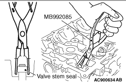
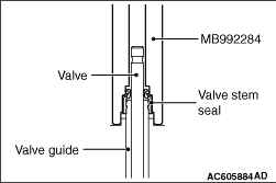
Use special tool valve stem seal pliers (MB992085) to nip the base of the stem seal (where
the outside diameter is larger) securely, and remove it by twisting it to the left and right.
|
|
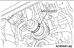
1.Mount the special tool installer inlet ring (MH062687) to the crankshaft, and set the
No. 1 cylinder top dead centre of its compression stroke.
|
|
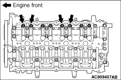
2.Loosen the adjust screws of the No. 1 and No. 3 exhaust rocker arm assemblies shown in
the figure.
3.Remove the exhaust rocker arm assembly.
4.Set cylinder No. 4 to the top dead centre of compression stroke.
|
|
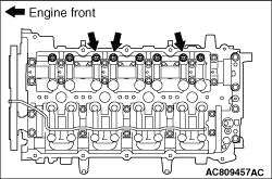
5.Loosen the adjusting screws of the No.2 and No.4 exhaust rocker arm assemblies shown in
the figure.
6.Slide the spherical surface of the adjusting screw from the pivot bolt, and remove
the exhaust rocker arm assembly.
|
|
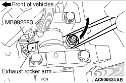
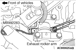
7.Remove the No. 4 exhaust rocker arm assembly as follows.
(1)
Turn the crankshaft clockwise from the No. 4 cylinder top dead centre of its compression
stroke by 180°. With this status, the cam nose faces upward.
(2)
Loosen the adjusting screw of the exhaust rocker arm assembly.
(3)
Screw in special tool retainer holder attachment (MB992090) to special tool valve spring
compressor (MD998772), and assemble special tool retainer holder D (MB992283).
(4)
|
|
| caution |
Note that the valve may fall into the cylinder when the retainer lock
comes off because the piston is not in the TDC position.
|
|
Install special tool MD998772 (with special tools MB992090 and MB992283 attached) to the
cylinder head, and compress the valve spring while avoiding the rocker arm.
(5)
Remove the exhaust rocker arm assembly from the gap between the cam and the cylinder inner
surface.
|
|
1.
| caution |
Valve stem seal for inlet valves and for exhaust valves are different.
Be sure to install the correct ones.
- Identification colour.
Exhaust valve stem seal: Green
|
Apply an adequate and minimum amount of engine oil to the valve stem seal.
|
|
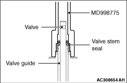
2.
| caution |
- Valve stem seal cannot
be reused.
- Special tool valve stem seal installer (MD998775) must be used to install the valve
stem seal. Improper installation could result in oil leaking past the valve guide.
|
Use special tool valve stem seal installer (MD998775) to fill a new valve stem seal in
the valve guide using the valve stem area as a guide.
Driving amount of exhaust valve stem seal: 19.8 mm
|
|
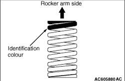
Install the valve spring with its identification colour painted end facing the locker
arm.
Identification colour
Inlet: Blue
Exhaust: Nothing
|
|
In the same manner as removal, use special tool valve spring compressor (MD998772) with
special tool retainer holder attachment (MB992090) and special tool retainer holder D (MB992283)
attached to compress the valve spring, and install the valve spring retainer lock.
|
|
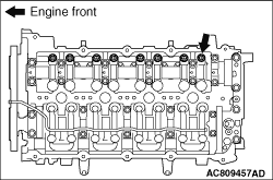
In the same removal manner as No. 4 exhaust rocker arm assembly shown in the figure, using
the special tool valve spring compressor (MD998772) to which the special tool retainer holder
attachment (MB992090) and special tool retainer holder D (MB992283) are assembled, compress
the valve spring and install the exhaust rocker arm.
|
|
1.
| caution |
Valve stem seal for inlet valves and for exhaust valves are different.
Be sure to install the correct ones.
- Identification colour.
Inlet valve stem seal: Grey
|
Apply an adequate and minimum amount of engine oil to the valve stem seal.
|
|
2.
| caution |
- Valve stem seal cannot
be reused.
- Special tool valve stem seal installer (MB992284) must be used to install the valve
stem seal. Improper installation could result in oil leaking past the valve guide.
|
Use special tool valve stem seal installer (MB992284) to fill a new valve stem seal in
the valve guide using the valve stem area as a guide.
Driving amount of inlet valve stem seal: 18.6 mm
|
|
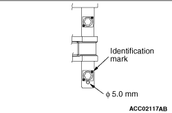
1.Install the rocker arm and shaft assembly so that the Φ5.0 mm holes of rocker
arm shaft face the cylinder head side.
2.Check that the identification marks on the rocker arm and shaft assembly are on the
position shown in the figure.
3.Tighten the rocker arm and shaft mounting bolts to the specified torque.
Tightening torque: 31 ± 3 N·m
|
|
|
1.Completely remove the sealant adhered to camshaft bearing rear cap and the cylinder
head installation side of the camshaft bearing rear cap, and degrease them with the volatile
degreasing agent.
|
|
2.
| caution |
- Remove the excessive sealant at the supply pump assembly
mounting hole and the vacuum pump assembly mounting hole using a rag or the like.
- After the installation, until a sufficient period of time (one hour or more) elapses,
do not apply the engine oil or water to the sealant application area or start the engine.
|
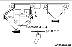
Apply the sealant with a diameter of 2 mm to the camshaft bearing rear cap as shown in
the figure.
Specified sealant: ThreeBond 1217G or equivalent
| note |
Install the camshaft bearing rear cap immediately after applying sealant.
|
|
|
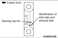
3.Install the camshaft bearing caps to the cylinder head.
| note |
Because the camshaft bearing thrust cap and camshaft bearing cap are the same in shape,
check the bearing cap number and additionally its symbol to identify the inlet and exhaust sides
for correct installation.
|
4.Tighten each camshaft bearing cap mounting bolt to the specified torque in the order
of number shown in the figure in two or three steps.
Tightening torque:
M6: 11 ± 1 N·m
M8: 20 ± 1 N·m
|
 ).
).)
)
)
)
)
)
)
)
)
)
)
)
)
)
)
)
)
)
)