|
|
1.Remove the common rail assembly mounting bolts.
|
|
|
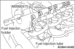
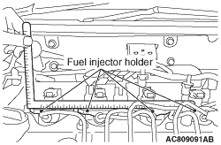
2.Loosen the fuel injector holder bolt completely.
|
|
3.Set the special tool hanger set (MB992675) into the fuel injector holder as shown.
| note |
As special tool MB992675 is hard to be inserted into fuel injectors No.1 and No.4, tilt
the fuel injector holder.
|
|
|
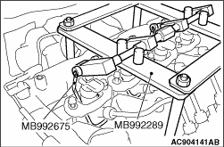
4.Remove the rocker cover mounting bolts as shown to assemble the special tool injector
and fuel pipe remover (MB992289).
|
|
5.Hook the arm of special tool MB992289 into special tool MB99267.
|
|
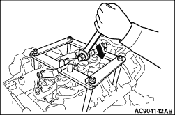
6.Swing the arm towards you to pull out the fuel injector from the cylinder head.
7.Remove special tools MB992289 and MB992675.
8.
| caution |
Protect the tip of the fuel injector nozzle with rag
to place the fuel injector and common rail assembly.
|
Remove the fuel injector and common rail assembly.
|
|
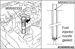
1.Insert the special tool nozzle gasket remover (MB992333) to the fuel injector mounting
hole on the cylinder head.
2.Rotate the dial of the tool as shown, and then pull out the tool while holding the
fuel injector nozzle gasket.
|
|
|
1.Remove the sealant from the rocker cover assembly, the matching area of the cylinder
head and timing chain case, and the matching area of the cylinder head and camshaft bearing
cap rear, and degrease them with the volatile degreasing agent.
|
|
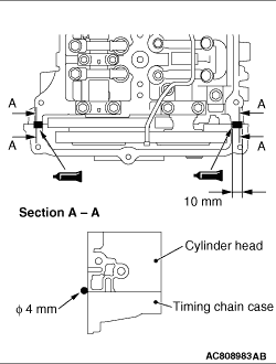
2.To the joints between the cylinder head and the timing chain case, apply the sealant with
a diameter of 4 mm as shown in the figure.
Specified sealant: ThreeBond 1217G or equivalent
|
|
3.
| caution |
- Remove the excessive sealant at the supply pump assembly
mounting hole and the vacuum pump assembly mounting hole using a rag or the like.
- After the installation, until a sufficient period of time (one hour or more) elapses,
do not apply the engine oil or water to the sealant application area or start the engine.
|
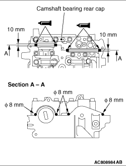
To the joints between the cylinder head and the camshaft bearing rear cap, apply the sealant
with a diameter of 8 mm as shown in the figure.
Specified sealant: ThreeBond 1217G or equivalent
| note |
Install the rocker cover assembly immediately after applying sealant.
|
|
|
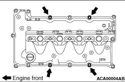
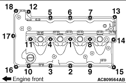
4.Tighten the rocker cover assembly mounting bolts to the specified torque in the order
of number shown in the figure.
Tightening torque: 3.0 ± 1.0 N·m
5.Tighten again the rocker cover assembly mounting bolts to the specified torque in
the order of number shown in the figure.
Tightening torque: 5.5 ± 0.5 N·m
|
|
|
1.Clean the fuel injector assembly (nozzle portion) and the cylinder head (fuel injector
mounting hole) (Refer to GROUP 13D - Fuel Injector  ). ).
|
|
|
2.
| caution |
Insert the fuel injector assembly securely.
|
Install the fuel injector assembly.
|
|
|
3.Tighten the fuel injector and common rail mounting bolts loosely while holding the
fuel injectors.
|
|
4.Seat the right and left fuel injector holder mounting bolts at the same time. Make sure
that the fuel injector holder is placed within 2 mm in the horizontal axis by using a L-shaped
steel scale.
5.Tighten the engine front side bolts of the fuel injector holder to 1.1 ± 0.1
N·m.
| note |
If the tool interferes with fuel return line hose C when tightening the fuel injector
holder bolts, remove fuel injection tube joint B (Refer to GROUP 13D - Fuel Injector ).
|
|
|
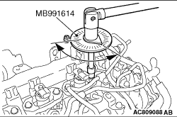
6.Use the special tool angle gauge (MB991614) to tighten the engine rear side bolts of the
fuel injector holder to 180° ± 1°.
7.Use the special tool (MB991614) to tighten the engine front side bolts of the fuel
injector holder to 90° ± 1°.
8.Tighten the common rail assembly to the specified torque.
Tightening torque: 25 ± 7 N·m
|
)
)
)
)
)
)
)
)
)
)
)