|
|
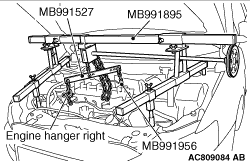
Install a special tool for holding the engine and transmission assembly.
|
|
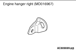
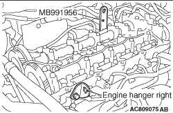
1.Install the engine hanger right (MD016967) to the cylinder head.
|
|
2.Install the special tool engine hanger plate (MB991956) to the cylinder head.
|
|
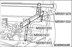
3.<When special tool engine hanger (MB991928) is used>
(1)
Assemble special tool engine hanger (MB991928). (Set the following
parts on the base hanger.)
- Slide bracket (HI)
- Joint x 2 (50) (MB991929)
- Joint x 2 (90) (MB991930)
- Joint x 2 (140) (MB991931)
- Foot x 2 (standard) (MB991932)
- Foot x 2 (short) (MB991933)
(2)
Set the foot of the special tool as shown in the figure.
|
|
| note |
Slide the slide bracket (HI) to adjust the engine hanger balance.
|
|
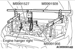
(3)
Mount special tool hanger (MB991527) to the engine hanger, and set it to special tool
MB991928 to support the engine and transmission assembly.
|
|
4.<When special tool engine hanger (MB991895) is used>
(1)
Set the foot of special tool engine hanger (MB991895) as shown in the figure.
|
|
| note |
Slide the foot to adjust the engine hanger balance.
|
|
(2)
Mount special tool hanger (MB991527) to the engine hanger, and set
it to special tool MB991895 to support the engine and transmission assembly.
|
|
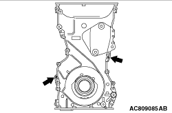
Remove the timing chain case assembly mounting bolts, then screw in the M6 x 1.0 bolt
to the area of the timing chain case assembly shown in the figure, and then remove the timing chain
case assembly from the cylinder head and cylinder block.
|
|
|
1.
| caution |
- Be sure to remove the sealant remaining
in the mounting hole, O-ring groove, and gap between parts.
- After degreasing with degreasing agent, check that there is no oil on the surface
where the sealant is applied.
- After degreasing with degreasing agent, never touch the degreased area with fingers.
|
Remove sealant from the timing chain case assembly and the timing chain case assembly
mounting surface of the cylinder block and the cylinder head, and degrease the surface where
the sealant is applied.
|
|
|
2.Remove all the sealant adhering to the gasket between the cylinder head and cylinder
block (three-surface aligned part.) Then, degrease the surfaces.
|
|
|
3.As for the three-surface aligned part that is indicated in Step 2 above, the engine
oil oozes from the cylinder head gasket. Thus, quickly apply the sealant to it after degreasing.
|
|
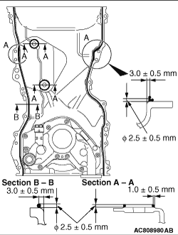
4.Apply a bead of the sealant to the timing chain case assembly mounting surface. The bead
diameter should be 2.5 ± 0.5 mm. Overlap the part "A" with the diameter of 2.5 ± 0.5
mm as shown in the figure, and apply the sealant.
Specified sealant: ThreeBond 1217G or equivalent
5.
| caution |
- When installing the
timing chain case assembly, make sure that the O-ring is fitted into the groove securely.
- If the sealant contacts any other part during installation of the timing chain case
assembly, apply sealant again before installing the timing chain case assembly.
- After the installation, until a sufficient period of time (one hour or more) elapses,
do not apply the oil or water to the sealant application area or start the engine.
|
Install the timing chain case assembly to the cylinder block and cylinder head so that
the sealant does not contact other parts.
| note |
Install the timing chain case assembly immediately after applying sealant.
|
|
|
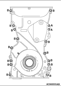
6.Install the timing chain case assembly mounting bolts to the installation positions shown
in the figure, and tighten them to the specified torque.
|
|
Bolt (Symbol)
|
Diameter × length mm
|
A
|
6 × 16
|
B
|
6 × 20
|
|
Tightening torque: 11 ± 3 N·m
|
|
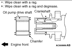
1.After wiping off the dirt on the oil pump drive shaft as shown in the figure using a rag,
degrease the area.
| note |
Degrease them to prevent drop in the friction coefficient of the pressed area, which is
caused by oil adhesion.
|
2.Install the oil pump drive shaft with the chamfered side facing the crankshaft side.
|
 ).
).)
)
)
)
)
)
)
)
)
)