|
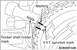
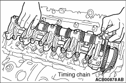
1.Align the mark for removal and installation of the rocker arm and camshaft assembly on
the V.V.T. sprocket with the mark on the rocker shaft holder, and then mark the timing chain.
|
|
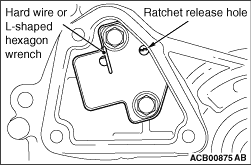
2.Insert a precision flat-tipped screwdriver through the service hole on the timing chain
case to release the timing chain tensioner ratchet.
3.While counterholding the crankshaft, tension the timing chain tensioner side of the
chain by turning the flats of the camshaft end in direction of engine rotation to compress the plunger.
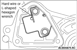
4.Insert hard wire (such as the piano wire) or the L-shaped hexagon wrench (1.5 mm)
to fix the plunger of the timing chain tensioner.
5.
| caution |
Be careful not to drop the timing chain tensioner mounting bolts
into the timing chain case.
|
Remove the timing chain tensioner.
6.Remove the timing chain from the V.V.T. sprocket.
|
|
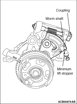
1.
| caution |
- To avoid damage, be careful not to apply torque exceeding
3 N·m when rotating the coupling.
- Do not hit the worm wheel against the minimum lift stopper too strongly.
- Never loosen the minimum lift stopper.
|
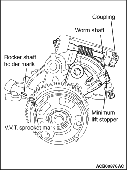
Rotate the coupling clockwise until the worm wheel contacts the minimum lift stopper slightly.
| note |
When rotating the coupling clockwise, the worm wheel should move in the minimum lift direction.
When rotating the coupling anti-clockwise, the worm wheel should move in the maximum lift direction.
|
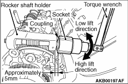
| note |
When rotating the coupling by hand, insert a 12-point socket (24 mm) into the position
on the coupling approximately 5 mm away from the rocker shaft holder. Then use a small torque
wrench to rotate it slowly.
|
|
|
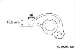
2.Pull down the adjusting screw of the exhaust side rocker arm at least to the shown dimension.
3.Loosen the mounting bolts of the rocker arm and camshaft assembly, and remove them.
|
|
4.Lift off the V.V.T. sprocket, the rocker arm and camshaft assembly from the cylinder head
while loosening the timing chain.
|
|
|
For the removal procedure, refer to GROUP 11D - Rocker Arm and Camshaft  . .
|
|
|
For the installation procedure, refer to GROUP 11D - Rocker Arm and Camshaft .
|
|
1.Pull down the adjusting screw of the exhaust side rocker arm at least to the shown dimension.
|
|
2.
| caution |
- To avoid damage, be careful not to apply torque exceeding
3 N·m when rotating the coupling.
- Do not hit the worm wheel against the minimum lift stopper too strongly.
- Never loosen the minimum lift stopper.
|
Rotate the coupling clockwise until the worm wheel contacts the minimum lift stopper slightly.
| note |
When rotating the coupling clockwise, the worm wheel should move in the minimum lift direction.
When rotating the coupling anti-clockwise, the worm wheel should move in the maximum lift direction.
|
| note |
When rotating the coupling by hand, insert a 12-point socket (24 mm) into the coupling
ca. 5 mm away from the rocker shaft holder. Then use a small torque wrench to rotate it slowly.
|
3.Align the mark for removal and installation of the rocker arm and camshaft assembly
on the V.V.T. sprocket with the mark on the rocker shaft holder.
4.Completely remove the sealant adhering to the cylinder head and the rocker arm/camshaft
assembly using a remover or others and degrease the area using a volatile degreasing agent.
|
|
5.
| caution |
The rocker arm and camshaft assembly cannot be installed with
the rocker arms hanging down.
|
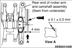
Apply sealant to the underside of the rocker arm and camshaft assembly without a gap and
immediately install the V.V.T. sprocket, rocker arm and camshaft assembly to the cylinder head.
Specified sealant: ThreeBond 1217G or equivalent
|
|
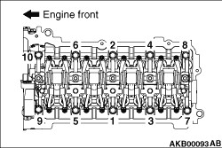
6.Temporarily tighten the mounting bolts of the rocker arm and camshaft assembly to 8.0
N·m in the order shown in the figure.
7.
| caution |
- After installation, wipe off excessive sealant thoroughly from
the sealant application area.
- After the installation, until a sufficient period of time (one hour or more) elapses,
do not apply the oil or water to the sealant application area or start the engine.
|
Tighten the mounting bolts of the rocker arm and camshaft assembly to the specified torque
in the order shown in the figure.
Tightening torque: 22 ± 3 N·m
|
|
1.Align the timing chain mark made during removal with the mark for removal and installation
of the rocker arm and camshaft assembly on the V.V.T. sprocket.
|
|
2.
| caution |
Be careful not to drop the timing chain tensioner mounting bolts
into the timing chain case.
|
Assemble the timing chain tensioner, and tighten the mounting bolts to the specified torque.
Tightening torque: 11 ± 3 N·m
3.Remove the hard wire or L-shaped hexagon wrench fixing the plunger of the timing chain
tensioner to apply tension to the timing chain.
|
)
)
)
)
)
)
)
)
)
)
)