|
1.
| caution |
- When rotating the coupling, do not apply the torque more
than 3 N·m to prevent the damage.
- Do not forcibly push the worm wheel to the minimum lift stopper and the maximum
lift stopper.
- Never loosen the minimum lift stopper.
|
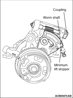
Slowly rotate the coupling clockwise. When lightly touching the worm wheel to the minimum
lift stopper, stop the worm wheel at the position shown in the illustration.
| note |
When rotating the coupling clockwise, the worm wheel should move in the minimum lift direction.
When rotating the coupling anti-clockwise, the worm wheel should move in the maximum lift direction.
|
| note |
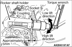
When manually rotating the coupling, insert a 12-point socket (24 mm) into the position
on the coupling approximately 5 mm away from the rocker shaft holder. Connect the mini torque
wrench and slowly rotate them.
|
|
|
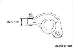
2.Adjust the rocker arm’s adjusting screw at the exhaust side to be less than the
dimension shown in the illustration.
3.Loosen and remove the bolts installing the rocker arm & camshaft assembly.
4.Lift the V.V.T. sprocket and the rocker arm and camshaft assembly and remove them
from the cylinder head.
|
|
|
Remove the nuts and adjusting screws from the rocker arm.
|
|
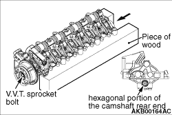
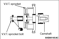
1.As shown in the illustration, mount the rocker arm and camshaft assembly on the piece
of wood.
2.Holding the hexagonal portion of the camshaft rear end, remove the V.V.T. sprocket
bolt.
|
|
|
Only when the dowel pin is pulled out from the camshaft for removing the V.V.T. sprocket,
install the dowel pin, according to the following procedures.
|
|
1.
| caution |
- When installing the dowel pin, pay attention
to the rocker arm and camshaft assembly not to be damaged.
- When installing the dowel pin, do not apply the load to the cam journal cam thrust
face.
|
Set the dowel pin straightly to the installation hole of the camshaft.
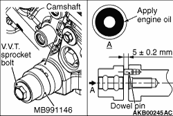
2.As shown in the illustration, apply an adequate and minimum amount of engine oil to
the lower flange of the V.V.T. sprocket bolt and the threads of the V.V.T. sprocket bolt, also
to the portion at the camshaft sprocket bolt side of the special tool installer (MB991146).
3.As shown in the illustration, set the special tool and the V.V.T. sprocket bolt.
4.Prevent the hexagonal portion of the camshaft rear end from rotating. Paying attention
to the dowel pin not to be tilted, tighten the V.V.T. sprocket bolt and press-fit the dowel
pin to 5 ± 0.2 mm.
|
|
1.Assemble the V.V.T. sprocket assembly in the following procedure.
(1)
Make sure that the dowel pin of the inlet camshaft assembly is positioned facing straight
upward.
(2)
Apply an adequate and minimum amount of engine oil to the lower flange of the V.V.T.
sprocket bolt and the threads of the V.V.T. sprocket bolt, as well as to the outer circumference
of the camshaft top end and all circumferences of the insertion portion of the V.V.T sprocket
assembly.
(3)
Slowly insert the inlet V.V.T. sprocket assembly into the normal position of the inlet
camshaft assembly with its knock pin hole facing straight upward.
2. Install the V.V.T sprocket to the camshaft.
3. Securely insert the V.V.T sprocket into the furthest part.
|
|
4.As shown in the illustration, mount the rocker arm and camshaft assembly on the piece
of wood.
5.Holding the hexagonal portion of the camshaft rear end, check that the V.V.T sprocket
assembly does not rotate.
6.Holding the hexagonal portion of the camshaft rear end, tighten the V.V.T sprocket
bolt to the specified torque of 77 ± 6 N·m.
|
|
1.Adjust the rocker arm’s adjusting screw at the exhaust side to be less than the
dimension shown in the illustration.
|
|
2.
| caution |
- When rotating the coupling, do not apply the torque more
than 3 N·m to prevent the damage.
- Do not forcibly push the worm wheel to the minimum lift stopper and the maximum
lift stopper.
- Never loosen the minimum lift stopper.
|
Slowly rotate the coupling clockwise. When lightly touching the worm wheel to the minimum
lift stopper, stop the worm wheel at the position shown in the illustration.
| note |
When rotating the coupling clockwise, the worm wheel should move in the minimum lift direction.
When rotating the coupling anti-clockwise, the worm wheel should move in the maximum lift direction.
|
| note |
When manually rotating the coupling, insert a 12-point socket (24 mm) into the position
on the coupling approximately 5 mm away from the rocker shaft holder. Connect the mini torque
wrench and slowly rotate them.
|
3.Align the overhaul and installation marks for the V.V.T. sprocket rocker arm and camshaft
assembly with the mark of the rocker shaft holder.
4.Rotate the camshaft clockwise by approximately 15 degree so that the intake valve
cannot be lifted.
5.
| caution |
- Use isopropyl alcohol to degrease. Then check that liquid
gasket application surface and recesses are not contaminated with oil or grease.
- Do not touch the part to be degreased as fingerprints may affect sealing performance.
|
Completely remove the liquid gasket adhered to the rocker arm and camshaft assembly and
the cylinder head, and then degrease by white gasoline.
|
|
6.
| caution |
Install the V.V.T. sprocket, the rocker arm and camshaft assembly
to the cylinder head within 3 minutes of applying the liquid gasket.
|
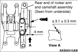
Apply the bead of 3.1 ± 0.3 mm liquid gasket to the position as shown in the
illustration.
Specified sealant:
ThreeBond 1217G or equivalent
|
|
7.
| caution |
After installation, wipe off excessive sealant thoroughly from
the sealant application area.
|
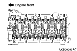
Tighten the rocker arm and camshaft assembly installation bolt in the sequence shown to
temporary torque of 8.0 N·m.
8.Tighten the rocker arm and camshaft assembly installation bolt in the sequence shown
to specified torque of 22 ± 3 N·m.
|
|
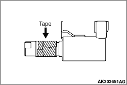
1.
| caution |
- The O-ring must not be reused.
- Wind non-adhesive tape (seal tape, etc.) around the notch of the oil passage of
the oil feeder control valve before installing the O-ring to prevent damage. Damage to the O-ring
causes oil leakage.
|
Apply a small amount of engine oil to the O-ring of the oil feeder control
valve.
2.Install the oil feeder control valve on the cylinder head.
3.Tighten the oil feeder control valve to the specified torque of 10 ± 2 N·m.
|
)

)
)
)
)
)
)
)
)
)