|
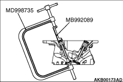
Use a special tool to compress the valve spring and to remove the retainer lock.
- Valve spring compressor (MD998735)
- Retainer holder C (MB992089)
| note |
Store removed parts such as valves and springs with tags describing cylinder No. and installed
position attached for reassembly.
|
|
|
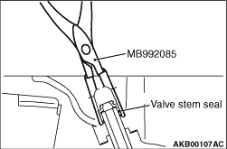
Use special tool Valve stem seal pliers (MB992085) to firmly pinch the base (larger external
shape) of the stem seal and twist it right and left for pulling out.
|
|
|
Use a special tool to install the valve stem seal, obeying the following procedures:
|
|
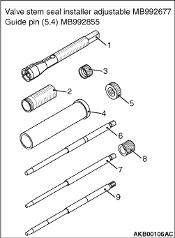
1.The special tool valve stem seal installer adjustable (MB992677) is composed of the components
shown in the illustration. Use special tool guide pin (5.4) (MB992855) to install the valve
stem seal.
1: Chuck
2: Sleeve
3: Rock nut (small)
4: Outer pipe
5: Rock nut (large)
6: Guide pin (5.9)
7: Guide pin (4.9)
8: Cap
9:Guide pin (5.4)
|

|
2.Adjust the inside chuck diameter, obeying the following procedures.
(1)
Install the sleeve to the chuck as shown in the illustration.
(2)
Install the shoulder of the valve stem seal to the chuck, aligning with the outer
circumference line of the chuck as shown in the illustration.
(3)
Turn the sleeve to wring the chuck.
(4)
Stop the sleeve at the position where you can easily remove the valve stem seal by
hand.
(5)
Use the (small) rock nut to fix the sleeve.
|
|
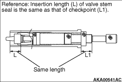
3.Adjust the stem seal insertion length, obeying the following procedures.
(1)
The position, in which the end face of the outer pipe is aligned with the outer circumference
line of the chuck, is 0 mm of the insertion length. Insert the chuck and the sleeve into the
outer pipe to fit the nut as shown in the illustration.
(2)
Turn the chuck to adjust the valve stem seal insertion length.
|
|
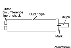
| note |
The insertion length can change by 1 mm per the chuck turn.
To easily know how many times the chuck is turned, put the mark at the position shown
in the illustration.
|
|
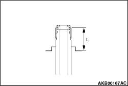
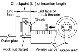
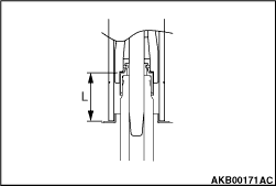
(3)
Use a vernier caliper to measure the checkpoint (L1) of the insertion length shown in
the illustration. Check the insertion length.
- Inlet side: 16.8 mm
- Exhaust side: 21.4 mm
(4)
Use the (large) rock nut to fix the sleeve.
|
|
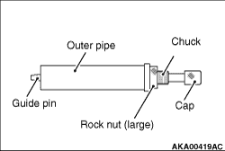
4.Install the cap to the guide pin (5.9).
5.Install the guide pin (5.9) as shown in the illustration.
6.Apply the engine oil to the valve stem seal to set the chuck.
7.Install the valve spring seat.
|
|
8.Use the plastic hammer to insert the valve stem seal.
|
|
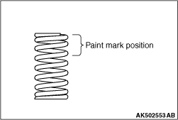
Install the inlet valve spring so that its painted side faces the rocker arm side.
| note |
The exhaust valve springs can be fitted either way up.
|
|
|
Use a special tool to compress the valve spring and to install the retainer lock.
- Valve spring compressor (MD998735)
- Retainer holder C (MB992089)
|
|
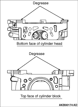
1.Completely remove the liquid gasket on the upper plane of the cylinder block and the lower
plane of the cylinder head.
2.
| caution |
Sufficiently check that there is no residual oil on the
place where degreasing is performed. If fingerprints are left, do not touch it with bare hands
after the degreasing, since the oils from your fingers will harm the seal ability.
|
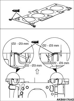
Use white gasoline to degrease the place specified in the illustration.
|
|
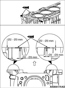
3.As shown in the illustration, apply a 2 - 3 mm of sealant to the top face of
cylinder block.
Specified sealant:
ThreeBond 1217G or equivalent
4.Install the cylinder head gasket.
| note |
Check that the centre of the liquid gasket is located toward the cylinder gasket in the
position specified in the illustration.
|
|
|
5.As shown in the illustration, apply a 2 - 3 mm of sealant to the top face of
cylinder head gasket.
Specified sealant:
ThreeBond 1217G or equivalent
6.Install the cylinder head assembly.
|
|
|
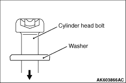
1.Install new cylinder head bolts and washers in the following procedure.
| note |
Cylinder head bolts and washers must not be reused.
|
|
|
2.Apply an appropriate amount of engine oil to top and bottom surfaces of washers and threaded
portion of bolts.
3.Install cylinder head bolts to the cylinder head.
|
|
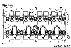
4.Tighten cylinder head bolts in several steps to the specified torque of 35 ± 2
N·m according to the assembly order.
|
|
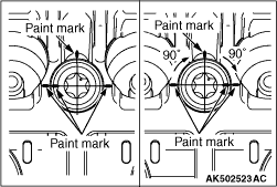
5.Put a paint mark on all of cylinder head bolt heads and cylinder head.
6.
| caution |
- When the tightening
angle is smaller than the specified tightening angle, the appropriate tightening capacity cannot
be secured.
- When the tightening angle is larger than the specified tightening angle, remove
the bolt to start from the beginning again according to the procedure.
|
Tighten the cylinder head 90° according to the tightening order.
Tighten it further 90° and make sure that the paint mark on the cylinder head
bolt is in a straight line with that on the cylinder head.
|
)

)
)
)
)
)
)
)
)
)
)
)
)
)
)
)
)
)