|
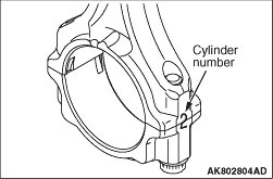
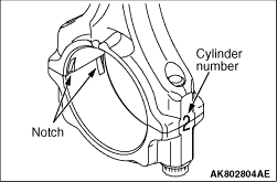
Write the cylinder No. on the connecting rod big end for the reinstallation.
|
|
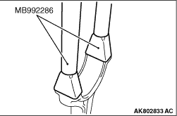
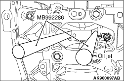
1.Not to damage the crank pin, install Special Tool Connecting Rod Guide (MB992286) to the
connecting rod.
2.Remove the piston connecting assembly from the cylinder block.
|
|
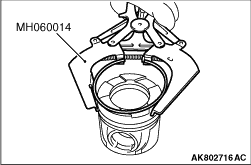
Use Special Tool Piston Ring Tool (MH060014) to remove the piston ring.
|
|
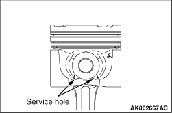
| caution |
When removed from the piston, the circlip can suddenly jump
out. Be careful.
|
Insert the precise screwdriver into the service hole to remove the circlip.
|
|
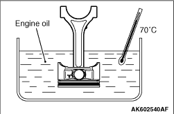
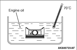
| caution |
The clearance between the piston and the piston pin is a tight
fit at room temperature. Therefore, be sure the heat the piston before pulling out the piston
pin. Use care sine the piston is hot after heating.
|
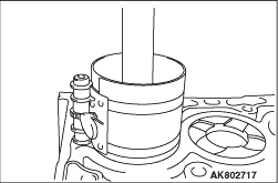
1.Into each container, pour enough engine oil to completely cover a piston.
2.Heat the engine oil to warm the piston to approximately 70°C, and then remove
the piston pin.
| note |
After pulling the piston pin out, organize the piston, the piston pin and the connecting
rod per cylinder No.
|
|
|
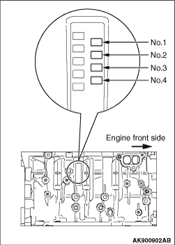
1.When replacing a piston, check the cylinder bore size mark stamped on the illustrated
position of the cylinder block and select a corresponding piston from the table below.
|
|
Cylinder bore size mark
|
Piston size mark
|
A
|
A
|
B
|
B or None
|
C
|
C
|
|
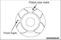
| note |
The piston size mark is indicated on the piston top face.
|
|
|
| caution |
The clearance between the piston and the piston pin is a tight
fit at room temperature. Therefore, be sure the heat the piston before pulling out the piston
pin. Use care sine the piston is hot after heating.
|
2.Into each container, pour enough engine oil to completely cover a piston.
3.Heat the engine oil to warm the piston to approximately 70°C, and then remove
the piston pin.
4.Sufficiently apply the engine oil to the outer circumference of the piston pin and
the small end hole of connecting rod.
|
|
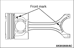
5.Put the front mark of connecting rod and the front mark of piston toward the same side,
and then insert the piston pin.
|
|
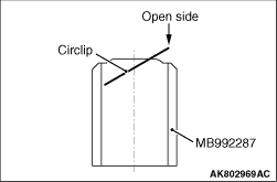
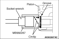
6.Install the circlip to the piston according to the following procedures:
(1)
With the open side facing upward, install the new circlip to Special Tool Circlip
installer (MB992287).
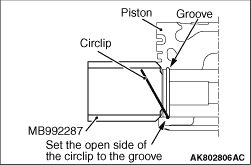
(2)
Align the open side of circlip with the piston groove, and then set the circlip together
with Special tool circlip installer.
(3)
|
|
| note |
Use the socket wrench whose outside diameter is Φ31 and whose drive angle is
12.7sq. If the socket wrench is too small, the snap ring cannot be engaged.
|
|
Push the opposite side of open side with the socket wrench #23 to install the
circlip to the piston groove.
(4)
Make sure the circlip is seated into the groove.
(5)
Unless seated into the groove, push the circlip with the socket wrench #23
again to seat it into the groove.
7.Make sure the piston smoothly rotates.
|
|
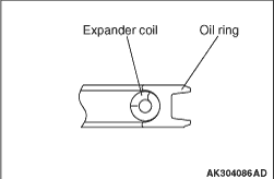
Install the expander coil and oil ring to the piston ring groove.
|
|
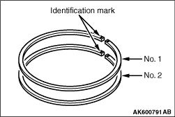
Use Special tool Piston ring tool (MH060014) to assemble piston rings with their identification
marks facing upward.
|
|
Identification mark:
No. 1 ring: 1T
No. 2 ring: 2T
|
|
|
1.Apply a sufficient amount of engine oil to the outer circumference of the piston,
piston rings and oil ring.
|
|
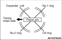
2.Arrange end gap positions of piston rings and oil ring (expander coil and oil ring) as
shown in the illustration.
|
|
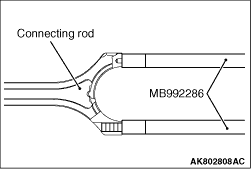
3.Install Special tool Connecting rod guide (MB992286) to the connecting rod.
|
|
| caution |
- Driving it in hard causes breakage of piston
rings and damage to the crank pin.
- When inserting the special tool, the special tool or the connecting rod must
not contact with the oil jet.
- Insert the piston and connecting rod assembly from the top surface of the
cylinder block with the front mark of the piston top face facing toward the timing belt side.
|
|
|
4.Firmly tighten the piston ring with a ring band and insert the piston connecting rod assembly.
|
|
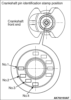
1.When replacing a connecting rod bearing, select the bearing corresponding to the crankshaft
pin outside diameter according to the crankshaft pin identification in the table below.
|
|
Crankshaft
|
Connecting rod bearing
|
Identification mark
|
Pin diameter mm
|
Identification colour
|
Identification mark
|
1
|
51.966 - 51.972
|
Black
|
1
|
2
|
51.960 - 51.966
|
None
|
2
|
3
|
51.954 - 51.960
|
Green
|
3
|
|
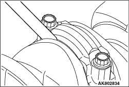
2.The identification mark of the crankshaft is stamped at the illustrated position per
No.
|
|
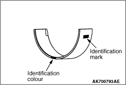
3.The connecting rod bearing has the identification colour at the illustrated position.
|
|
1.Assemble the bearing cap on the connecting rod by aligning it with the mark that was put
during removal. If a new connecting rod without a mating mark is used, assemble so that the
detent notch of the bearing is on the same side as illustrated.
|
|
2.Make sure that clearance of the thrust of the connecting rod big end is appropriate.
Standard value: 0.10 - 0.25 mm
Limit: 0.4 mm
|
|
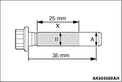
1.Check in the following procedure before reusing the connecting rod bolt.
(1)
Measure the largest outside diameter "A".
(2)
Measure the smallest outside diameter "B" within the range "X" shown in the illustration.
(3)
If the difference of outside diameter of thread exceeds the limit, replace the connecting
rod bolt.
Limit: 0.1 mm
2.Apply engine oil to the threaded portion and seat surface of the bolt before installing
the bolt.
3.After installing each bolt and tightening it by fingers, tighten bolts alternately
to properly assemble the cap.
4.Tighten the bolt to the torque of 5.0 N·m.
5.Tighten the bolt to the torque of 20 N·m.
|
|
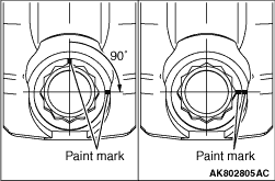
6.Put a paint mark on the bolt head as illustrated.
7.Put the paint mark on the connecting rod at 90° position in the tightening
direction of the bolt, based on the paint mark position of the bolt.
| caution |
- When the tightening angle
is smaller than the specified tightening angle, the appropriate tightening capacity cannot be
secured.
- When the tightening angle is larger than the specified tightening angle, remove
the bolt to start from the beginning again according to the procedure.
|
8.Tighten the bolt 90°, and make sure that the paint mark of the connecting
rod is aligned with that of the bolt.
|
)

)
)
)
)
)
)
)
)
)
)
)
)
)
)
)
)
)
)
)
)
)
)
)
)